
Selecting the correct filler metal is critical in TIG Welding Filler Rod Selection Chart usage because it directly affects weld integrity, arc stability, and compatibility with the base metal.
A mismatch between filler rod and parent material can lead to poor fusion, cracking, corrosion issues, or failed inspections, especially in precision applications like stainless steel or aluminum welding.
A properly structured selection chart helps welders match filler composition with base metal type, shielding gas, and welding parameters such as amperage and heat input.
This reduces the risk of defects like porosity, lack of penetration, and excessive distortion, while improving overall weld strength and appearance.
Understanding how to read and apply a filler rod selection chart ensures consistent results across different materials and joint conditions. This guide will clarify how to interpret these charts accurately and apply them in real welding scenarios to improve performance and reduce costly rework.
How TIG Filler Rod Composition Drives Weld Integrity
Every TIG rod carries an AWS designation that encodes its exact chemical limits and intended performance. The “ER” prefix means electrode or rod; the following numbers and letters lock in minimum tensile strength, chemistry, and deoxidizer package.
AWS Classification System Breakdown
- Carbon steel rods fall under AWS A5.18 (ER70S-x). The “70” guarantees 70,000 psi minimum tensile strength in the as-welded condition.
- Stainless rods use AWS A5.9 (ER308L, ER316L, etc.). The “L” suffix caps carbon at 0.03 % max to prevent sensitization and intergranular corrosion.
- Aluminum rods follow AWS A5.10 (ER4043, ER5356). Silicon or magnesium content directly controls fluidity, hot-crack resistance, and anodizing color match.
Deoxidizers and Alloying Elements in Carbon Steel Rods
Silicon and manganese levels decide puddle behavior. Higher silicon improves wetting and bead shape on mill-scale surfaces. Extra deoxidizers (zirconium, titanium, aluminum) in certain rods neutralize oxygen and nitrogen from light rust or poor fit-up.
These differences are not cosmetic—they determine whether the weld passes X-ray or bends 180° without cracking.
TIG Welding Filler Rod Selection Chart for Mild and Carbon Steel
Mild steel (A36, 1018, 1020) dominates shop and field TIG work. The two most common rods are ER70S-2 and ER70S-6. Both meet 70 ksi tensile, but their deoxidizer packages create distinct performance envelopes.
ER70S-2 vs ER70S-6: Performance Comparison
ER70S-2 contains triple deoxidizers (Zr, Ti, Al) plus low silicon. It excels on thin sheet, root passes, and lightly contaminated surfaces because the deoxidizers scavenge oxygen aggressively. Use it when the joint will see radiographic testing or when fit-up is marginal.
ER70S-6 carries higher silicon (0.80–1.15 %) and manganese. The extra silicon produces excellent fluidity, smooth bead contour, and strong wetting even on mill-scale plate. It is the default choice for production fabrication where speed and appearance matter.
Both rods are compatible with 100 % argon or argon/helium mixes. ER70S-6 tolerates slightly higher travel speeds without undercut.
Other ER70S Variants and When They Matter
ER70S-3 offers a middle ground for clean plate at higher production rates. ER80S-D2 is required for 4130 chromoly tubing when the assembly will be heat-treated—its higher strength and lower ductility prevent cracking during post-weld stress relief. Never substitute ER70S-6 for ER80S-D2 on normalized 4130; the weld will under-match the base metal.
Stainless Steel TIG Filler Rod Selection Chart
Stainless demands exact carbon control and alloy balance to preserve corrosion resistance.
Matching ER308L, ER316L, and ER309L to Base Grades
- ER308L joins 304, 304L, 321, and most 300-series austenitics. Low carbon prevents carbide precipitation in the heat-affected zone.
- ER316L adds 2–3 % molybdenum for superior pitting resistance in chloride environments—marine hardware, chemical valves, pharmaceutical tubing.
- ER309L serves as the transition rod when joining stainless to carbon steel. Its higher chromium and nickel content compensates for dilution and prevents martensite formation at the interface.
Low-Carbon “L” Designations and Real Corrosion Performance
The “L” grade limits carbon to 0.03 % maximum. In service above 800 °F or in acidic environments, standard-carbon rods form chromium carbides that deplete the grain boundaries and trigger intergranular attack. Always verify the base metal spec; if it is 304L or 316L, the filler must also carry the “L” suffix.
Aluminum TIG Welding Filler Rod Selection Chart
Aluminum selection is more complex than steel because alloy families behave differently in the weld pool.
ER4043 vs ER5356: Strength, Fluidity, and Anodizing Match
ER4043 (5 % silicon) delivers superior fluidity, lower melting point, and reduced crack sensitivity. It is the go-to rod for 6xxx series (6061, 6063) and castings. Bead appearance is smooth and it tolerates minor oxide inclusions better.
ER5356 (5 % magnesium) produces higher as-welded strength and better ductility. It is required for 5xxx series (5052, 5083, 5086) where structural loads or marine exposure dominate. However, it is more prone to hot cracking if joint fit-up is poor and does not anodize to the same color as 4043 on 6xxx base metal.
Using the Aluminum Filler Selection Matrix for 5xxx and 6xxx Alloys
Consult the Hobart-style matrix for critical properties:
- 6061 plate: ER4043 or ER4943 (4943 adds magnesium for 10–15 % higher strength).
- 5052 or 5083 sheet: ER5356 or ER5183 for maximum corrosion resistance and toughness.
- Elevated-temperature service (250–350 °F): Switch to ER5554 on 5454 base to avoid stress-corrosion cracking.
- Post-weld heat treat required: ER4943 or ER2319 respond to solution treatment and aging far better than standard 4043.
Special Cases for Elevated Temperature or PWHT
Magnesium levels above 3 % in 5xxx fillers make them susceptible to sensitization at 150–350 °F. For heater brackets or exhaust components, the matrix clearly routes you to 5554 instead of 5356.
Filler Rod Diameter Selection Guide for TIG Welding
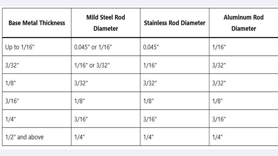
Rod diameter must balance heat input, puddle control, and deposition rate. The rule of thumb—rod diameter never exceeds base metal thickness—still holds, but practical tables refine it.
Thickness-Based Recommendations Across Metals
| Base Metal Thickness | Mild Steel Rod Diameter | Stainless Rod Diameter | Aluminum Rod Diameter |
|---|---|---|---|
| Up to 1/16″ | 0.045″ or 1/16″ | 0.045″ | 1/16″ |
| 3/32″ | 1/16″ or 3/32″ | 1/16″ | 3/32″ |
| 1/8″ | 3/32″ | 3/32″ | 3/32″ |
| 3/16″ | 1/8″ | 1/8″ | 1/8″ |
| 1/4″ | 3/16″ | 3/16″ | 3/16″ |
| 1/2″ and above | 1/4″ | 1/4″ | 1/4″ |
Adjusting for Joint Type and Amperage
Butt joints on thin material allow the smaller diameter. Fillet welds demand one size larger to fill the joint without multiple passes. Stainless requires one size smaller than carbon steel at the same thickness because you run lower amperage to avoid carbide precipitation. Aluminum puddles faster, so a 3/32″ rod on 1/8″ plate often feels easier than the same size on steel.
Advanced Factors in TIG Filler Rod Decisions
Dissimilar Metal Joins and Transition Rods
When 304 stainless meets A36 carbon steel, ER309L is mandatory. Its chemistry buffers dilution and stops hard martensite zones that crack under bending or vibration.
Shielding Gas Compatibility with Filler Chemistry
Pure argon works for all common rods. Helium additions (25–50 %) increase heat input and are useful with thicker aluminum when using ER5356, but they can widen the bead profile with high-silicon ER4043. Never use CO₂ or oxygen mixes with stainless or aluminum fillers; they destroy corrosion resistance instantly.
Interpreting Manufacturer TIG Filler Rod Charts
Every box of rod includes a heat number and AWS spec. Cross-reference the manufacturer’s online selector (Hobart, ESAB, or Washington Alloy) against your exact base alloy and service temperature. The charts reveal hidden requirements—such as 5554 for 5454 at 300 °F—that generic “use 5356” advice misses.
Real-World Application Insight
Selecting the correct TIG welding filler rod is a non-negotiable mechanical and metallurgical decision. Match the AWS classification to base metal chemistry, choose diameter by thickness and joint geometry, and verify service conditions (corrosion, temperature, post-weld heat treatment). Do this consistently and your welds will meet or exceed the parent metal’s strength and life expectancy every time.
The pro-level insight: In fatigue-critical applications, pressure vessels, aircraft frames, or high-cycle machinery—the filler rod’s ductility and toughness often become the limiting factor, not the base metal. ER5356 on 5083 or ER80S-D2 on 4130 can double fatigue life compared with a generic “close enough” rod. Treat the filler as an engineered component of the joint, not just filler metal.

Hi, I’m Zachary Ford. I’m passionate about welding and dedicated to helping both beginners and experienced welders make informed decisions. I research, test, and write about welding helmets, welding machines, safety equipment, and essential workshop tools. My goal is to provide honest reviews, practical buying guides, and easy-to-follow tutorials that help you weld more safely, work more efficiently, and choose the right gear with confidence.