
Welders run into real trouble when TIG welding stainless steel: beads that warp the part, heavy oxidation that ruins corrosion resistance, or lack of root fusion that fails inspection. These problems stem from one core issue—incorrect machine setup that fails to account for stainless steel’s low thermal conductivity and high sensitivity to oxygen at welding temperatures.
Mastering how to set up TIG welder for stainless steel fixes this by locking in DCEN polarity, exact gas coverage, matched tungsten, and thickness-specific amperage. The right configuration delivers clean, narrow heat-affected zones, straw-to-light-blue weld colors, and welds that pass dye-penetrant or pressure testing on the first try.
This guide delivers the exact parameters and decision points professionals and serious hobbyists use to dial in any inverter or transformer TIG machine for 304, 316, or other austenitic grades.
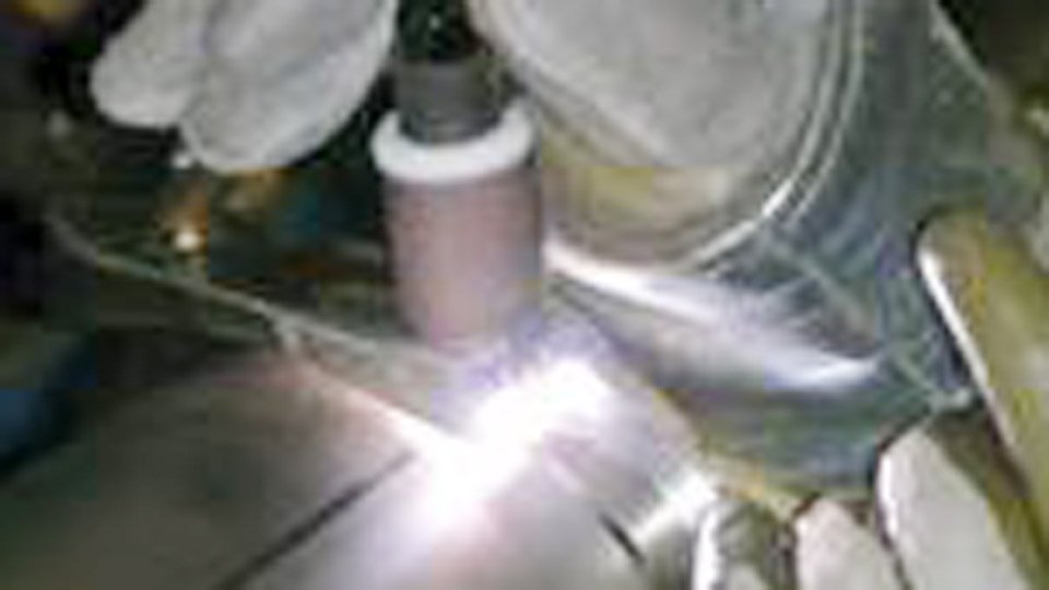
Image thefabricator
Selecting the Correct Polarity and Current Type
Stainless steel demands direct current electrode negative (DCEN) for TIG welding. DCEN concentrates 70% of the heat at the workpiece, producing deep penetration with minimal tungsten erosion and a focused arc cone that stainless steel responds to predictably.
Why DCEN Is Non-Negotiable for Stainless Steel
AC current introduces unnecessary oxide cleaning action that overheats thin stainless and widens the heat-affected zone. DCEN eliminates that, letting you run 10-20% lower amperage than on mild steel while still achieving full penetration.
Every modern TIG inverter offers a dedicated DCEN TIG mode; select it before powering up. Transformer machines require manual polarity switch confirmation—double-check the torch cable connects to the negative terminal.
Inverter vs Transformer Machines: Setup Differences That Matter
Inverter machines deliver stable output down to 5-10 amps, ideal for thin-gauge stainless under 0.060 inch. Set the output to DC TIG, enable high-frequency start, and confirm the machine recognizes the torch as negative.
Older transformer units run hotter and need slightly higher base amperage (add 5-10 amps) to compensate for less responsive output. Regardless of machine type, disable AC balance and any aluminum-specific waveforms before striking an arc on stainless.
Tungsten Electrode Selection and Preparation
The electrode forms the heart of the arc. Wrong alloy or diameter causes arc wander, tungsten contamination, or insufficient current-carrying capacity on stainless steel.
Optimal Tungsten Alloys for Stainless Steel TIG
2% lanthanated (blue) or 2% ceriated (gray) electrodes deliver the best balance of arc stability, low burn-off, and easy starts on stainless. They outperform pure tungsten and match or exceed 2% thoriated (red) without radioactivity concerns.
Lanthanated holds a sharp point longer during extended runs on 1/8-inch and thicker material. Avoid pure tungsten entirely—it balls and creates an unstable arc on DCEN.
Matching Electrode Diameter to Material Thickness
Electrode size must support the target amperage without overheating. Use this reference:
| Thickness (inches) | Recommended Tungsten Diameter | Max Amperage Capacity (DCEN) |
|---|---|---|
| 0.036–0.060 | 0.040–1/16 inch (1.0–1.6 mm) | Up to 150 A |
| 0.063–0.125 | 3/32 inch (2.4 mm) | Up to 250 A |
| 0.188–0.250 | 1/8 inch (3.2 mm) | Up to 400 A |
Select the smallest diameter that carries your planned amperage. Oversized tungsten reduces arc focus and increases the risk of contamination.
Grinding and Tip Geometry for Stable Arc
Grind the electrode longitudinally on a dedicated tungsten sharpener or diamond wheel. Create a taper no longer than 2.5 times the electrode diameter. Leave a flat tip of 0.010–0.030 inch (0.25–0.75 mm) depending on amperage—smaller flats for thin material, larger for thicker sections.
This geometry prevents the arc from wandering and reduces the chance of tungsten inclusions. Re-grind immediately if the tip dulls or picks up base metal.
Configuring Shielding Gas and Flow Parameters
Stainless steel oxidizes instantly above 800°F. Shielding gas decisions directly determine whether the weld stays bright silver or turns dull gray-black.
Choosing Argon or Argon/Helium Mixes
Pure argon (99.995% or better) remains the standard for stainless steel under 1/4 inch. It provides excellent coverage at moderate flow rates and keeps heat input manageable. For material thicker than 3/16 inch or when deeper penetration is required, switch to an argon/helium mix (75/25 or 50/50). Helium additions increase puddle fluidity and travel speed but raise overall heat input—reduce amperage by 10% when switching.
Setting Pre-Flow, Post-Flow, and Flow Rates
Set pre-flow to 1–2 seconds to purge the torch and joint before the arc starts. Post-flow is critical: run 1 second of post-flow for every 10 amps used, with a minimum of 8–10 seconds on stainless. On 100-amp welds, target 10–15 seconds; on 200-amp welds, extend to 20 seconds. Hold the torch in place over the cooling puddle during post-flow.
Typical flow rates with a gas lens:
| Cup Size | Flow Rate (CFH) | Best For |
|---|---|---|
| #7 | 12–18 | Thin material, tight spaces |
| #8 | 15–22 | Most stainless work |
| #10 | 20–25 | Thick material, high heat |
Gas Lens and Cup Selection for Superior Coverage
Install a gas lens collet body on every stainless job. It creates laminar flow that tolerates 1/2–3/4 inch stickout without turbulence, reducing gas consumption and improving access in tight joints. Pair the lens with a large ceramic cup (#8 or #10) to blanket the puddle and heat-affected zone effectively.
Determining Amperage Settings for Different Thicknesses
Amperage must balance penetration against distortion. Stainless retains heat far longer than mild steel, so settings run 10–20% lower.
Amperage Reference Table for Stainless Steel
Use these starting points on DCEN with a sharp tungsten and gas lens. Adjust live with the foot pedal.
| Thickness (inches) | Gauge | Butt Joint Amps | Fillet Joint Amps | Tungsten Size | Filler Size |
|---|---|---|---|---|---|
| 0.036 | 20 ga | 25–45 | 30–50 | 0.040–1/16″ | 0.045″ |
| 0.060 | 16 ga | 45–70 | 50–75 | 1/16″ | 1/16″ |
| 0.125 | 1/8″ | 80–120 | 90–130 | 3/32″ | 3/32″ |
| 0.188 | 3/16″ | 110–160 | 120–170 | 3/32″ | 1/8″ |
| 0.250 | 1/4″ | 140–200 | 150–220 | 1/8″ | 1/8″ |
These values assume 100% argon, clean material, and moderate travel speed. For open-root pipe or vertical-up, drop 10 amps and slow travel.
Using Foot Pedal for Real-Time Heat Control
Set the machine’s maximum amperage to the upper end of the range above and use the pedal to modulate from 20–30% at the start to full depression once the puddle forms. On stainless, back off the pedal as the part heats to prevent burn-through. Machines without a pedal require precise panel settings and faster travel speed.
Adjustments for Joint Types and Welding Positions
Butt joints need slightly lower amperage than fillets because heat concentrates in one plane. Vertical-up welding requires 10–15% reduction and a tighter arc length (1/8 inch max) to control the puddle. Overhead demands the lowest amperage in the range plus a gas lens to maintain shielding against gravity.
Choosing and Preparing Filler Rods
Filler must match the base alloy chemistry to preserve corrosion resistance and mechanical properties.
Filler Metal Matching to Stainless Grades
- 304/304L base → ER308L filler
- 316/316L base → ER316L filler
- Dissimilar stainless or stainless-to-mild → ER309L
Keep filler in a dedicated stainless-only rod pouch. Clean each rod with acetone and a lint-free cloth immediately before use.
Rod Diameter and Feed Technique Decisions
Choose filler diameter 0.010–0.020 inch smaller than base thickness for thin material and equal to or slightly larger for thicker sections. Feed the rod at a 15–20° angle into the leading edge of the puddle, dipping only when the puddle is fluid. On pulse settings, add filler during the high-amperage peak only.
Torch Assembly and Advanced Machine Settings
Proper torch configuration turns good parameters into repeatable high-quality welds.
Assembling the TIG Torch for Stainless Work
Install the gas lens collet body, matching collet, and ceramic cup. Set electrode stickout to 1/8–1/4 inch for most work—longer stickout is possible with the gas lens. Torch angle: 10–15° push angle for flat and horizontal; 45° for fillets. Use a water-cooled torch above 150 amps to maintain consistent gas flow and prevent overheating.
Pulse TIG Parameters for Heat Management
Pulse TIG excels on stainless thinner than 1/8 inch. Set peak amperage at your normal setting, background at 30–50% of peak, pulse frequency 1–2 pulses per second for thin sheet or 50–150 PPS for stacked dimes on thicker material.
Pulse width 40–60%. This reduces average heat input by 30–40% while maintaining penetration and producing a stacked-dime appearance.
Upslope and Downslope for Clean Starts and Stops
Set upslope to 1–2 seconds to ramp from 10–20 amps to main amperage, preventing cold starts and tungsten contamination. Downslope 2–4 seconds to taper current and fill the crater without cracking. On 316L especially, always add filler at the end of downslope to chill the puddle.
Verifying Your Setup Before Striking the Arc
Run a 10-second gas purge to confirm flow and check torch connections. Strike a test arc on scrap of the same thickness and alloy. Look for a tight, cone-shaped arc, immediate puddle formation, and no tungsten spitting. Adjust flow or amperage one variable at a time until the test bead shows even ripple, full penetration (if visible), and straw-to-light-blue color.
Final Thoughts
Stainless steel TIG welding rewards precise machine setup more than any other material. Lock in DCEN, match tungsten and amperage to thickness using the tables above, install a gas lens with adequate post-flow, and control heat with the foot pedal or pulse.
These decisions deliver welds that maintain the base metal’s corrosion resistance, pass visual and non-destructive testing, and require minimal cleanup.
The next time you face a critical stainless assembly—whether a food-grade tank, exhaust system, or architectural panel—you will know exactly how to set up TIG welder for stainless steel and produce pro-level results on the first pass.

Hi, I’m Zachary Ford. I’m passionate about welding and dedicated to helping both beginners and experienced welders make informed decisions. I research, test, and write about welding helmets, welding machines, safety equipment, and essential workshop tools. My goal is to provide honest reviews, practical buying guides, and easy-to-follow tutorials that help you weld more safely, work more efficiently, and choose the right gear with confidence.