
Getting Pulse MiG Welding Stainless Steel Settings right is critical for achieving consistent penetration, controlled heat input, and a clean, low-spatter finish. Pulse transfer changes how current cycles between peak and background amperage, directly affecting arc stability, droplet transfer, and distortion control, especially on thin or heat-sensitive stainless sections.
Incorrect settings can lead to lack of fusion, excessive oxidation, or costly rework due to warping and poor bead profile.
This is not a trial-and-error process at the professional level. Shielding gas mix, wire feed speed, pulse frequency, and voltage balance must work together within a narrow window to maintain a stable arc and proper wetting action.
Understanding how these variables interact in real welding conditions helps prevent defects that often fail visual or code inspection.
In this guide, you’ll get a clear, performance-focused breakdown of how to dial in settings that produce repeatable, high-quality stainless steel welds.
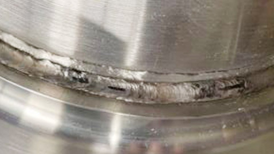
Image reddit
Why Pulse MIG Delivers Superior Results on Stainless Steel
Pulse transfer controls the arc at the millisecond level, unlike constant-voltage spray that floods the puddle with continuous high amperage. Lower average heat input directly reduces warping on thin panels or dissimilar-thickness repairs while maintaining full fusion.
Spatter drops dramatically because the background phase allows the droplet to detach cleanly without explosive short circuits, cutting cleanup time by half in shop environments.
Heat Input Control to Prevent Distortion and Sugaring
Stainless expands and contracts more than mild steel, so even 10 percent extra heat creates visible bow or cracks at the heat-affected zone. Pulse settings keep the average amperage 15-25 percent below equivalent spray values for the same deposition rate.
On 0.090-inch 304 sheet, this means running 110-130 average amps instead of 160-180, eliminating the need for copper backing or extensive fixturing. Sugaring—the black oxide scale on the back side—disappears when heat input stays below 15-18 kJ/in because the pulsed arc never overheats the root.
Spatter Reduction and Bead Appearance
Pulse produces a stacked-dime ripple with minimal oxidation lines when the waveform matches the gas and wire. Real-world tests on 316L show spatter reduced to near zero compared with standard MIG, which throws globules that embed in the bead and require chipping.
The result is a flat-to-convex profile that wets evenly without undercut, critical for sanitary tubing or pressure vessels where dye-penetrant inspection must pass on the first try.
All-Position Capability Without Compromising Fusion
Vertical and overhead welds on stainless traditionally demand short-circuit mode with its cold laps and lack of fusion. Pulse maintains spray-like transfer at travel speeds up to 18 ipm in vertical-up while the background current prevents puddle runoff. This lets fabricators skip TIG root passes on pipe or frames, boosting productivity without sacrificing radiographic quality.
Choosing Consumables That Match Pulse MIG Stainless Settings
Consumable selection locks in the baseline for stable pulsing. Wrong wire or gas forces constant overrides that waste time and risk defects.
Wire Diameter and Alloy Selection
Use 0.030-inch or 0.035-inch ER308LSi or ER316LSi for 90 percent of stainless work. The high-silicon LSi variants improve wetting and tie-in under pulsed current, reducing cold laps on 304 to 316 transitions. Reserve 0.045-inch for plate over ¼ inch where higher deposition outweighs the slightly wider arc.
Match filler exactly: 308L for 304/304L base, 316L for 316/316L, and 309L only for dissimilar carbon-to-stainless. Never use standard ER308L in pulse—the lower silicon creates ropey beads and higher spatter regardless of trim setting.
Shielding Gas Blends for Clean Beads and Low Oxidation
98% Ar / 2% CO₂ is the go-to for most pulse MIG stainless because it stabilizes the arc at lower background currents while limiting carbon pickup. Tri-mix (90% He / 7.5% Ar / 2.5% CO₂) adds fluidity for thicker sections or vertical work, allowing 10-15 percent higher travel speed before the puddle sags.
Avoid 75/25 Ar/CO₂ entirely—it creates excessive oxidation and forces higher trim values that destabilize the pulse. Flow at 25-35 cfh with a ½-inch nozzle and ⅜-½ inch stickout; longer stickout kills pulse stability on stainless.
Contact Tip and Nozzle Recommendations
Recessed ¼-inch contact tips paired with ¾-inch gas cups maintain consistent arc length during pulse cycling. Stainless wire erodes tips faster than mild steel, so replace every 8-10 pounds of wire or when voltage fluctuates more than 0.5 V at the same trim setting.
Thickness-Specific Pulse MIG Stainless Steel Settings
Pulse parameters scale with thickness, but the goal remains constant: one droplet per pulse at the lowest average heat that achieves full penetration.
Thin Gauge Stainless (Under 0.125 Inch)
For 16-11 ga (0.060-0.125 inch) 304 or 316 sheet, start with 0.030-inch or 0.035-inch LSi wire at 180-280 ipm wire feed speed. Set trim or arc length control to 0 to +0.5 for a slightly longer arc that reduces burn-through risk. Peak current targets 280-350 A, background 40-70 A, frequency 120-180 Hz.
Travel speed 14-22 ipm in flat position keeps heat input under 12 kJ/in. These settings produce a ⅛-inch wide bead with stacked dimes and zero distortion on unsupported panels.
Medium Thickness Stainless (0.125 to 0.25 Inch)
At ⅛-¼ inch, increase to 240-380 ipm WFS on 0.035-inch wire. Trim drops to -0.5 to 0 for tighter arc and deeper penetration. Average amperage lands at 130-190 A. Pulse frequency 100-150 Hz balances bead width and ripple control.
Use 30-35 cfh tri-mix if vertical fillets are required; the helium component prevents the puddle from freezing before sidewall fusion. Expect 10-15 ipm travel speed with a 10-15° push angle to avoid undercut.
Heavy Plate Stainless (Over 0.25 Inch)
Switch to 0.045-inch wire at 180-320 ipm. Peak current rises to 380-450 A with background 80-120 A and frequency 80-120 Hz for larger droplets. Trim -1.0 to -0.5 tightens the arc for multi-pass groove welds. Travel speed slows to 8-12 ipm to manage heat buildup across passes.
Interpass temperature must stay below 350 °F—pulse alone cannot overcome poor technique here. These parameters deliver 20-30 percent higher deposition than short-circuit while keeping distortion manageable with proper sequencing.
| Thickness | Wire | WFS (ipm) | Trim | Avg Amps | Pulse Freq (Hz) | Travel (ipm) | Gas |
|---|---|---|---|---|---|---|---|
| <0.125″ | 0.035″ LSi | 180-280 | 0 to +0.5 | 80-140 | 120-180 | 14-22 | 98Ar/2CO₂ |
| 0.125-0.25″ | 0.035″ LSi | 240-380 | -0.5 to 0 | 130-190 | 100-150 | 10-15 | Tri-mix |
| >0.25″ | 0.045″ LSi | 180-320 | -1.0 to -0.5 | 180-280 | 80-120 | 8-12 | Tri-mix |
Adjust ±10 percent based on joint fit-up and machine calibration.
How to Fine-Tune Pulse Waveform for Stainless Steel
Modern inverters give direct access to waveform variables that standard MIG never touches.
Peak and Background Current Selection
Peak current must exceed the spray threshold (roughly 220-250 A for 0.035-inch wire) long enough to detach one droplet—typically 1.8-2.5 ms pulse width. Set background just high enough to maintain the arc (40-80 A) without adding unnecessary heat. Too low a background and the arc extinguishes; too high and you lose the heat-reduction benefit.
Pulse Frequency and Width Adjustments
Higher frequency (150-200 Hz) on thin material creates a narrow, stacked-dime bead ideal for cosmetic work. Lower frequency (80-120 Hz) on plate widens the bead and improves sidewall fusion in grooves. Pulse width trades off with frequency: shorter width at higher frequency keeps average heat minimal while still transferring metal.
Trim and Inductance for Bead Control
Trim (or arc length control) is the fastest way to dial appearance. Increase trim for a longer arc and flatter bead with less penetration; decrease for a tighter arc and deeper finger. Inductance or arc control softens the pulse rise time on machines that offer it, reducing spatter further on vertical runs.
What Adjustments Are Needed for Different Welding Positions?
Position changes the effective heat input because gravity affects puddle behavior.
Flat and Horizontal Pulse Settings
Flat fillets or grooves allow the most aggressive parameters—higher WFS and slightly negative trim for maximum speed. Gun angle 10-15° push keeps the arc in front of the puddle and prevents porosity.
Vertical and Overhead Pulse MIG Techniques
Drop WFS 15-20 percent and raise frequency 20 Hz to stiffen the puddle. Use a 5-10° downhill drag angle in vertical-up to control the molten pool. Overhead requires the shortest arc length (trim -1.0) and lowest background current to prevent drip. Travel speed must increase 10-15 percent to stay ahead of the puddle.
How to Troubleshoot and Optimize Pulse MIG Settings on Stainless
Even perfect starting parameters need verification on scrap.
Addressing Common Weld Defects
Lack of fusion shows as a dull line at the toe—raise peak current or shorten stickout. Porosity on the root usually means insufficient gas flow or dirty base metal; stainless demands acetone wipe plus stainless wire brush within 30 minutes of welding. Excessive spatter despite pulse indicates trim too high or wrong gas—switch to tri-mix and lower trim by 0.5.
Machine-Specific Calibration Tips
Miller and ESAB synergic programs for stainless require only material thickness and wire diameter input; fine-tune trim in 0.1 increments while watching the puddle. Lincoln Power Wave users benefit from the stainless pulse waveform preset, then adjust arc control -1 to -3 for smoother transfer.
Always verify actual amperage and voltage at the gun with a meter—machine displays can read 5-8 percent optimistic on pulse.
Real-World Application Insight
The correct pulse MIG stainless steel settings let you choose the exact heat input your project demands instead of fighting the process. Match wire, gas, and waveform to thickness and position once, then repeat the same numbers across shifts or jobs.
Professionals who master trim and frequency adjustments consistently produce welds that pass visual, dye-penetrant, and corrosion tests without extra labor.
The advanced insight: pair pulse with a 5-10 percent backstep technique on multi-pass stainless joints and you maintain the original material’s corrosion resistance in the heat-affected zone far better than any constant-current process ever could.

Hi, I’m Zachary Ford. I’m passionate about welding and dedicated to helping both beginners and experienced welders make informed decisions. I research, test, and write about welding helmets, welding machines, safety equipment, and essential workshop tools. My goal is to provide honest reviews, practical buying guides, and easy-to-follow tutorials that help you weld more safely, work more efficiently, and choose the right gear with confidence.