Wire feed interruptions are one of the fastest ways to ruin weld quality, and Hobart Welder Wire Feed Problems typically show up as inconsistent arc sound, erratic deposition, or sudden burn-backs. These issues directly affect penetration, bead uniformity, and amperage stability, which can lead to failed welds, excess spatter cleanup, or costly rework during inspection.
In real fabrication conditions, even a minor feed hesitation can shift heat input enough to distort thin material or weaken structural joints. Understanding what causes feed instability—whether it’s drive roll tension, liner drag, contact tip restriction, or spool resistance—is essential for maintaining arc control and production efficiency.
The following guidance focuses on diagnosing root causes quickly and applying practical corrections so your wire delivery stays smooth, predictable, and aligned with your machine’s output performance.
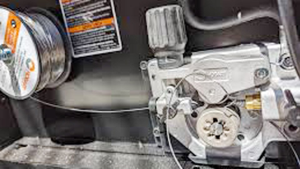
Photo reddit
Wire Feed System in Hobart Welders
Hobart’s wire feed mechanisms are designed for efficiency in entry-level to mid-range MIG units. The system typically includes a DC motor driving knurled or V-groove rolls, a liner conduit, and a contact tip assembly.
For instance, the Handler 140 features a wire feed speed range of 40–700 inches per minute (IPM), adjustable via a potentiometer, supporting wire diameters from 0.024 to 0.035 inches for solid wire and flux-cored variants.
The drive rolls apply pressure to advance the wire through the liner to the gun. Tension is set via a spring-loaded arm, typically requiring 1–2 turns for optimal grip without flattening the wire. Excessive tension can cause birdnesting—where wire bunches at the drive rolls—while insufficient grip leads to slipping and erratic feeding.
The liner, often a coiled steel or polymer tube, must be trimmed to length (usually 10–15 feet for standard guns) to minimize friction. Electrical control comes from the circuit board, which regulates motor speed based on the dial setting.
In professional setups, arc stability depends on consistent wire delivery at rates matching travel speed—typically 200–400 IPM for 0.030-inch wire on mild steel at 18 volts and 100 amps. Deviations here amplify problems like burnback, where wire melts back to the tip, or stubbing, where it bucks against the workpiece due to feed resistance.
Identifying Symptoms of Wire Feed Malfunctions
Wire feed issues manifest in distinct ways, each pointing to potential causes. Erratic feeding, characterized by pulsing or intermittent advance, often indicates drive roll misalignment or motor voltage fluctuations.
For example, if the wire advances smoothly without load but stutters under arc, check for voltage drops below 12–24 VDC at the motor terminals, common in models like the Handler 135.
Birdnesting appears as tangled wire at the feeder inlet, resulting from backlash when feed speed exceeds gun delivery. This is quantifiable: if tension allows wire slip exceeding 5% of feed rate, birdnests form rapidly.
No-feed scenarios, where the motor hums but no wire emerges, suggest seized components or open circuits. Overheating shutdowns, triggered by the internal thermostat at around 150–160°C, halt feeding after 10–15 minutes of high-duty cycle use, as seen in the Handler 175 during prolonged 1/4-inch plate welds.
Spatter buildup or poor arc starts tie back to inconsistent wire extension—ideally 3/8 to 1/2 inch beyond the nozzle.
Monitor for audible cues: a smooth whirring motor versus grinding indicates mechanical binds, while clicking solenoids without feed point to trigger faults.
Root Causes of Wire Feed Problems
Diagnosing requires isolating variables in the feed path. Start with mechanical inspections before electrical tests to avoid misattribution.
Drive Roll and Tension Assembly Issues
Drive rolls wear over time, with grooves flattening after 500–1,000 pounds of wire. Knurled rolls for flux-cored wire grip aggressively but can shave solid wire, reducing diameter by 0.002–0.005 inches and causing slip. Incorrect groove selection—using a 0.030-inch groove for 0.035 wire—increases resistance by 20–30%, leading to motor overload.
Tension settings are critical: too loose (under 0.5 turns) allows backlash; too tight (over 2 turns) deforms wire, raising friction in the liner. In Hobart units, the potentiometer controls motor RPM, but degraded contacts can cause speed variance of ±10–20 IPM, exacerbating these issues.
Liner and Conduit Blockages
Liners accumulate debris from wire coatings, spatter, or environmental dust, increasing drag force to 5–10 pounds. A kinked liner, often from gun mishandling, restricts flow, simulating a blockage. Polymer liners in extended guns (over 10 feet) flex more, but steel coils in standard setups provide better push for thicker wires.
Burrs at liner ends, formed during trimming, snag wire, causing intermittent stops. Quantify this: a clean liner allows pull-through with under 2 pounds of force; higher indicates replacement needed.
Contact Tip and Nozzle Wear
Worn contact tips develop oval bores, disrupting current transfer and causing arcing inside the tip. This leads to burnback, where wire fuses at 1,500–2,000°F. Spatter-laden nozzles restrict gas flow, reducing shielding efficiency and promoting erratic arcs that feedback to feed speed.
Tip life spans 50–100 pounds of wire, depending on amperage (e.g., 140 amps shortens it by 30%). Diffuser blockages amplify this, as uneven gas distribution affects arc cone stability.
Electrical and Control Components
Faulty potentiometers in models like the Handler 110 cause no-feed by failing to signal the board. Measure resistance: a healthy 10k ohm pot sweeps evenly; jumps indicate replacement.
Transistors on the control board, such as the TIP142 in some units, fail from heat or surges, cutting motor power. Brushes in DC motors wear to under 1/4 inch, increasing resistance and dropping speed. Wiring harness breaks, often at flex points, show as open circuits on multimeter tests.
Overheating and Protective Shutdowns
Hobart’s thermostat protects the transformer, opening at high temps and resetting after cooling with fan on. This halts feed but preserves components. Duty cycle exceedance—e.g., 20% at 90 amps on the 140—triggers this, as internal heat buildup exceeds dissipation rates.
Step-by-Step Diagnostic Process
Begin with safety: unplug the unit and discharge capacitors. Inspect visually for obvious damage.
- Test trigger continuity: Pull gun trigger and measure across leads; zero ohms confirms switch function.
- Check motor operation: Bypass trigger by shorting terminals; if motor runs, trace upstream. Measure voltage at motor: 12–24 VDC expected at mid-speed setting.
- Assess drive rolls: Remove wire, spin rolls manually; binding suggests bearing wear. Verify groove size and tension by feeding sample wire without arc.
- Evaluate liner: Disconnect gun, pull wire through; resistance over 2 pounds signals cleaning or replacement. Use compressed air at 30–40 PSI for debris removal.
- Inspect tip and nozzle: Replace if bore is non-round or spatter exceeds 1/8 inch buildup. Test for shorts between tip and nozzle.
- Electrical diagnostics: Use a multimeter for pot sweep (0–10k ohms linear), board output, and thermostat continuity (closed when cool).
If issues persist, consult model-specific schematics—available in manuals for the Handler series—to probe board components.
Implementing Repairs and Adjustments
Solutions prioritize minimal intervention for quick returns to service.
For drive rolls: Replace with OEM parts matching wire type—V-groove for solid, knurled for cored. Set tension to just prevent slip when pulling wire by hand.
Liner fixes: Trim ends square with a file, deburr, and blow out. Replace if kinks exceed 5 degrees. Use anti-spatter spray sparingly to avoid residue buildup.
Tip and nozzle: Swap tips every 50 pounds; clean nozzles with pliers or reamers. Ensure tip size matches wire (e.g., 0.030 for 0.030 wire) for optimal current density.
Electrical repairs: Solder broken wires; replace pots (common 10k linear) or transistors (TIP142 equivalents). For brushes, disassemble motor and install new sets, ensuring commutator cleanliness.
Overheating: Improve ventilation, adhere to duty cycles (e.g., 20% on 140 means 2 minutes weld per 10), and clean internal fans annually.
In one shop case, erratic feeding on a Handler 175 traced to a degraded pot; replacement restored precise 100–500 IPM control, improving bead consistency on 1/8-inch joints.
Preventive Maintenance for Long-Term Reliability
Regular upkeep extends feed system life. Monthly: Clean drive rolls with a wire brush, inspect liner for wear, and test tension.
Quarterly: Blow out unit with compressed air, check electrical connections for corrosion, and calibrate speed against a tachometer if available.
Store wire spools covered to prevent contamination, which increases drag. Use quality wire with low cast (under 1 inch helix per foot) to minimize liner friction. For high-volume use, upgrade to longer-lasting polymer liners.
Track usage: Log wire consumed and note anomalies to predict failures, like tip wear accelerating at higher amps.
Wrapping Up
In preventing wire feed problems, focus on setup precision from the start. Proper polarity—DCEP for MIG—ensures stable arc transfer, reducing feedback issues. Joint preparation with clean edges minimizes spatter sources that propagate to the feed path.
This approach not only resolves current faults but builds resilience. An advanced insight: Monitor wire feed amperage draw; spikes over 2–3 amps signal impending mechanical binds, allowing preemptive action before full failure.
FAQ’s
Why does my Hobart Handler 140 stop feeding wire after a few minutes?
This likely indicates thermostat activation from overheating. Allow cooling with the fan running for 10–15 minutes. Check duty cycle adherence and ensure adequate ventilation; clean internal components if buildup restricts airflow.
How do I fix birdnesting in my Hobart welder?
Reduce drive roll tension slightly and inspect the contact tip for burrs or wear. Ensure the liner is straight and clean; replace if drag exceeds normal. Match wire diameter to groove precisely to avoid backlash.
What causes erratic wire speed in the Handler 135?
Degraded potentiometer contacts often culprit this. Test resistance sweep; replace if uneven. Also, verify motor voltage stability and clean brushes if under 1/4 inch length.
Is a worn liner the main reason for no wire feed?
Not always—check trigger wiring first for opens. If motor runs but wire doesn’t advance, liner blockages or kinks are probable. Pull-test the wire through the disconnected gun to confirm.
How often should I replace drive rolls in Hobart MIG welders?
Every 500–1,000 pounds of wire, or sooner if grooves flatten. Inspect quarterly for shaving or slipping signs, especially with flux-cored wire on knurled rolls.