Setting the correct amperage is one of the most critical factors in TIG welding performance. A TIG Welding Amps to Metal Thickness Chart helps welders match current output to the material thickness, ensuring proper penetration, arc stability, and weld pool control.
When amperage is too low, the arc struggles to penetrate the base metal, often leading to weak fusion and cold welds. Too much amperage, on the other hand, can cause burn-through, excessive heat input, distortion, and unnecessary rework.
Because TIG welding offers precise heat control, selecting the right amperage range becomes especially important when working with thin sheet metal, stainless steel, or aluminum components.
Fabricators, hobbyists, and shop technicians frequently rely on amperage charts to establish a reliable starting point before fine-tuning based on joint design, travel speed, and electrode size.
Understanding how amperage relates to metal thickness allows welders to produce cleaner welds, reduce defects, and maintain consistent quality across different materials and fabrication conditions.
Why Amperage Selection Determines Weld Integrity
Heat input in TIG is governed by the equation:
Heat Input (kJ/in) = (Amps × Volts × 60) / Travel Speed (ipm)
Arc voltage in TIG typically sits between 10–15 V depending on arc length and gas. Travel speed on manual TIG averages 4–8 ipm. This means amperage becomes the primary lever for controlling penetration depth.
On 0.125 in (3.2 mm) mild steel, 100 A DCEN at 6 ipm delivers approximately 1.0–1.2 kJ/in—enough for full penetration without melt-through on a properly prepared joint. Drop to 70 A and penetration drops below 50 %; raise to 140 A and the puddle becomes uncontrollably fluid with undercut risk.
Material thermal conductivity further modulates the required amperage. Mild steel dissipates heat moderately. Stainless steel retains heat (lower thermal conductivity), requiring 10–15 % less amperage to avoid warping.
Aluminum conducts heat rapidly and forms a tenacious oxide layer, demanding 20–30 % higher amperage plus AC polarity to break the oxide and establish a stable puddle before the heat escapes.
Key Variables That Shift Base Amperage Values
Material Type and Heat Conductivity
Mild steel follows the industry baseline of approximately 1 A per 0.001 in of thickness for butt joints. Stainless steel runs cooler in the arc because heat stays localized—reduce baseline by 10–15 %. Aluminum requires the highest amperage because the oxide layer (melting point ~3700 °F) must be shattered by the AC cleaning cycle before the base metal (melting point ~1220 °F) pools.
Tungsten Electrode Diameter and Current Capacity
Undersized tungsten overheats and erodes; oversized tungsten produces a diffuse arc with poor directional control. Use the following capacity limits (argon shielding, 70 % DCEN or balanced AC):
- 1/16 in (1.6 mm) tungsten: 50–150 A DCEN / 60–120 A AC
- 3/32 in (2.4 mm) tungsten: 100–250 A DCEN / 100–180 A AC
- 1/8 in (3.2 mm) tungsten: 150–350 A DCEN / 160–250 A AC
Exceed these limits and the electrode contaminates the weld or the arc becomes unstable.
Joint Configuration and Welding Position
Butt joints in flat position use the base chart values. Fillet joints require +10–20 A because the heat spreads into two planes. Vertical-up demands +15–25 A to counteract gravity-induced puddle sag. Overhead requires –10–15 A with faster travel to prevent dripping.
Shielding Gas Flow and Cup Size
Argon at 15–20 CFH for steel/stainless; 20–25 CFH for aluminum. Gas lens bodies reduce required flow by 20–30 % while improving coverage. Helium mixes increase heat input 20–30 %, allowing slightly lower amperage for the same penetration on thick aluminum.
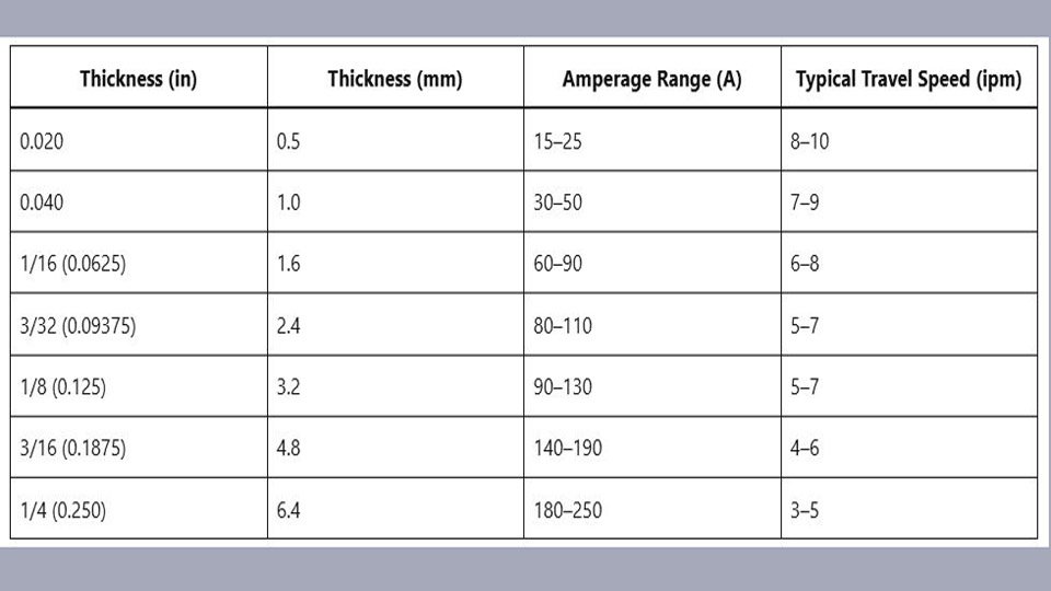
TIG Welding Amps to Metal Thickness Chart – DCEN (Mild Steel)
These values assume 2 % thoriated or lanthanated tungsten, pure argon, flat-position butt joints, and 1/16–3/32 in filler rod. Start at the low end and increase with foot-pedal control.
| Thickness (in) | Thickness (mm) | Amperage Range (A) | Typical Travel Speed (ipm) |
|---|---|---|---|
| 0.020 | 0.5 | 15–25 | 8–10 |
| 0.040 | 1.0 | 30–50 | 7–9 |
| 1/16 (0.0625) | 1.6 | 60–90 | 6–8 |
| 3/32 (0.09375) | 2.4 | 80–110 | 5–7 |
| 1/8 (0.125) | 3.2 | 90–130 | 5–7 |
| 3/16 (0.1875) | 4.8 | 140–190 | 4–6 |
| 1/4 (0.250) | 6.4 | 180–250 | 3–5 |
TIG Welding Amps to Metal Thickness Chart – DCEN (Stainless Steel)
Reduce mild-steel values by 10–15 % because stainless retains heat. Use 2 % lanthanated tungsten and back-purge for root passes on pipe or thin sheet.
| Thickness (in) | Thickness (mm) | Amperage Range (A) |
|---|---|---|
| 0.020 | 0.5 | 15–22 |
| 1/16 (0.0625) | 1.6 | 50–75 |
| 1/8 (0.125) | 3.2 | 80–110 |
| 3/16 (0.1875) | 4.8 | 130–170 |
| 1/4 (0.250) | 6.4 | 160–220 |
TIG Welding Amps to Metal Thickness Chart – AC Aluminum
ACHF (AC high frequency) with 20–25 % electrode negative balance for penetration. Pure or zirconiated tungsten. Preheat sections thicker than 1/4 in to 300 °F to stabilize the puddle.
| Thickness (in) | Thickness (mm) | Amperage Range (A) |
|---|---|---|
| 0.040 | 1.0 | 35–55 |
| 1/16 (0.0625) | 1.6 | 65–90 |
| 1/8 (0.125) | 3.2 | 120–160 |
| 3/16 (0.1875) | 4.8 | 170–220 |
| 1/4 (0.250) | 6.4 | 220–280 |
Tungsten Electrode Diameter vs Amperage Capacity Chart
Match electrode diameter to current to maintain arc stability and prevent tungsten spitting.
| Tungsten Diameter | Max DCEN Amps (Argon) | Max AC Amps (Balanced) |
|---|---|---|
| 0.040 in (1.0 mm) | 70 | 60 |
| 1/16 in (1.6 mm) | 150 | 120 |
| 3/32 in (2.4 mm) | 250 | 180 |
| 1/8 in (3.2 mm) | 350 | 250 |
Polarity and AC Balance Settings for Penetration Control
DCEN concentrates 70–80 % of heat into the workpiece—ideal for steel and stainless. AC for aluminum alternates between cleaning (electrode positive) and penetration (electrode negative).
Set balance control to 65–75 % electrode negative on modern inverters for deeper penetration without excessive cleaning. Higher cleaning percentage (lower negative) widens the arc but reduces penetration depth by 15–20 %.
Practical Application: Integrating the Chart with Machine Technique
Dial the chart value as your peak amperage on pulse or foot-pedal machines. For pulsed TIG on stainless, set background at 40–50 % of peak to control heat input while maintaining puddle fluidity.
On aluminum, use a foot pedal aggressively—ramp up quickly to establish the puddle, then modulate down 20–30 A once oxide is cleared to prevent melt-through.
Travel speed must increase proportionally with amperage; every additional 10 A typically requires 0.5–1 ipm faster travel to maintain the same bead width.
One shop-proven technique on 1/8 in aluminum: begin at 140 A to shatter the oxide, then immediately drop to 110–120 A once the puddle forms. This prevents undercut while delivering full penetration in a single pass.
On multi-pass welds thicker than 3/16 in, drop amperage 10–15 A per subsequent pass. Heat accumulates in the joint; maintaining the same amperage widens the HAZ and promotes distortion.
Diagnosing Amperage-Related Defects
Insufficient amperage produces a narrow, convex bead with lack-of-fusion at the toes and a tight, constricted arc. Increase amperage 10–15 A and shorten arc length to 1/16 in maximum.
Excessive amperage creates a concave bead with undercut, tungsten spitting, or burn-through holes. Reduce amperage 15–20 A, increase travel speed, or switch to a larger tungsten for better arc stiffness.
Porosity on stainless or aluminum almost always traces to low amperage combined with inadequate gas coverage—raise amperage slightly and verify 20+ CFH flow with a gas lens.
Performance Summary and Advanced Insight
The TIG Welding Amps to Metal Thickness Chart delivers repeatable fusion across production runs when paired with correct tungsten size, polarity, and travel speed. Operators who internalize these ranges and adjust in real time via foot-pedal control produce X-ray-quality welds with minimal post-weld cleanup.
Advanced insight: once base amperage is locked to thickness, overlay synchronized pulse (1–2 Hz, 50–70 % peak duration) on stainless or aluminum.
This reduces average heat input by 25–35 % while maintaining full penetration—critical for thin-wall tubing or aerospace-grade stainless where distortion tolerance is measured in thousandths of an inch.
Wrapping Up
These settings, refined across thousands of production hours on inverter machines, translate directly to cleaner beads, reduced distortion, and fewer defects in any shop. Keep the charts laminated near your power source—precision welding begins with precise amperage.
FAQs
What amperage for 1/8 inch mild steel TIG weld?
90–130 A DCEN with 3/32 in lanthanated tungsten. Start at 100 A flat butt joint; add 10–15 A for fillets or vertical position.
How many amps for 1/8 inch aluminum TIG?
120–160 A AC with 65–75 % electrode negative balance. Use 3/32 in zirconiated tungsten and 20–25 CFH argon.
Does stainless steel TIG require different amps than mild steel?
Yes—reduce mild-steel values by 10–15 % (80–110 A for 1/8 in) because stainless retains heat. Use lanthanated tungsten and back-purge to prevent sugaring.
What tungsten size for 100 amps TIG welding?
3/32 in (2.4 mm) diameter. It safely handles 100–250 A DCEN or 100–180 A AC without overheating or arc wander.
Why does aluminum need more amps than steel of the same thickness?
Aluminum’s high thermal conductivity dissipates heat rapidly, and the oxide layer requires AC cleaning action. Result: 20–30 % higher amperage plus faster puddle establishment to achieve fusion before the base metal cools.