A Lincoln welder wire feed motor not working kills productivity fast—trigger pull yields gas flow and sometimes a relay click, but no wire advances, no arc starts, and you’re stuck chasing downtime in the middle of a job.
This hits common models like the Weld-Pak 140/180 series, Power MIG 210, Pro-MIG 175, and older SP/HH lines hardest, especially in home shops and small U.S. fabrication setups where machines see irregular use and accumulate dust or old grease.
The issue stems from the wire feed system’s low-voltage DC motor (typically 12–24 V control) failing to receive or respond to command. Downtime costs real money when you’re mid-project on structural repairs or custom fab, and repeated failures point to neglected maintenance rather than random bad luck.
Systematic diagnosis isolates whether the problem lies in input signal, control circuitry, motor itself, or mechanical bind—most cases resolve without full board replacement if you follow voltage checks and mechanical teardown first.
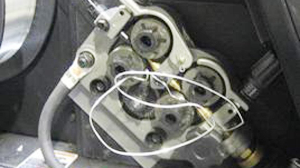
Image by thefabricator
Symptom Breakdown: What You’re Actually Hearing and Seeing
Power on, fan spins, gas solenoid clicks when trigger pulled—that rules out main power supply and basic trigger circuit in many cases. No motor hum or drive roll rotation means zero torque at the gearbox. Occasional chatter or weak spin at high speed settings points to partial voltage but insufficient current or mechanical drag.
Relay click without motion isolates the issue downstream of the trigger circuit—control board output, wiring, or motor/gearbox. If drive rolls turn freely by hand with tension released but bind under load, suspect seized gears or old lubricant. Motor spins freely on direct 12 V battery but not in-machine signals control-side failure.
Step-by-Step Voltage and Continuity Checks
Unplug the machine and discharge capacitors before opening the case—use a multimeter on DC volts.
Verify trigger signal first. Disconnect gun leads at the Euro connector or internal terminals; jumper the trigger pins (typically two small wires) to simulate pull. If motor runs, replace the gun switch or repair torch wiring—common on abused 15–25 ft guns.
Next, probe motor terminals directly at the board output while triggering. Expect 10–30 V DC proportional to wire speed knob setting (higher voltage at max speed). Zero or <1 V indicates no output from control board—check input power to board (often fused 120/240 V line side), rectifier diodes for corrosion, and any inline fuses (many Lincoln units have 3–5 A fast-blow on control transformer secondary).
If voltage present but motor silent, disconnect motor wires and apply 12 V DC battery directly. Spins freely → wiring or polarity issue (reverse leads if direction wrong). No spin → bad motor windings or brushes. Measures 5–20 ohms across terminals typical for good PMDC motor.
Mechanical Inspection: Gearbox and Drive System Failures
Many Lincoln compact MIGs (Weld-Pak/Pro-MIG 140–180 class) suffer seized gear trains from hardened factory grease after 5–10 years or low-use storage. Symptom: motor hums weakly or stalls under load; drive rolls won’t budge even with tension off.
Remove motor/gearbox assembly (usually four screws, part L7801 style on older units—replacements scarce). Disassemble cover (Torx T20), clean out black, chunky grease with degreaser and small brush. Inspect plastic gears for stripped teeth—replace if damaged, but most survive cleaning.
Apply fresh high-temp lithium or synthetic grease (NLGI 2), reassemble, and test rotation direction (swap motor wires if reversed).
Drive roll tension overtightened flattens wire and overloads motor—set to just prevent slip (wire should mark slightly but not deform). Wrong groove size for wire diameter binds feed; match V-groove to 0.030–0.035″ solid or knurled for flux-cored.
Spool brake too tight causes coasting stop then stall on restart—loosen until spool stops within 1–2 turns after trigger release.
Control Board and Component-Level Issues
Control boards fail from heat, dust ingress, or voltage spikes. Look for burnt resistors near motor drive transistors, cracked solder joints, or swollen electrolytics in power section.
Common on 140/180 series: rectifier leads corrode at tabs—resolder or replace diodes (1N5408 equivalents). Potentiometer (wire speed knob) wiper fails intermittently—clean with contact spray or replace (10k linear typical).
If board receives power but no output, test SCR or MOSFET driver circuit—beyond DIY for most, but swapping known-good board from similar model confirms.
Fuses blow from seized motor drawing stall current (10–20 A spikes)—replace with same rating after fixing bind.
Model-Specific Notes for Lincoln Units
Weld-Pak/Pro-MIG 140/180/HH 140: Grease-bound gearbox most reported; clean first before buying parts.
Power MIG 210/256: Better duty cycle but board corrosion from shop humidity common—seal case better if dusty environment.
Older SP-135/140T: Voltage selector switch loose connections interrupt control power—wiggle knob or resolder.
Pro-MIG 175: Solenoid click but no feed often bad board or trigger bypass test isolates.
Practical Prevention to Avoid Repeat Failures
Run machine monthly even if idle—prevents grease hardening. Store upright, dry, dust-free. Use quality wire to reduce drag. Clean liner every 100–200 lbs wire; replace if kinked. Set tension conservatively and match components (tip, liner, rolls) to wire type/diameter.
Two shop-floor insights: First, on 140-series units, always check wire speed knob isn’t at absolute zero—some models cut motor power below a threshold detent. Second, when cleaning gearbox, mark motor wire polarity before disassembly—reversing rotation jams wire backward and strips drive rolls.
Diagnostic-First Resolution and Long-Term Reliability Insight
Wire feed motor failure in Lincoln welders traces to four fixable categories: no command signal (trigger/board/fuse), insufficient voltage/current (wiring/corrosion), mechanical bind (grease/gears), or dead motor. Start with trigger bypass and direct motor test, move to voltage probe at terminals, then mechanical teardown—90% resolve before touching the board.
The advanced insight that keeps machines running decades: treat the wire feed as a torque-limited system. Monitor stall behavior early—any hum without rotation means drag exceeding available torque.
Address bind immediately rather than cranking tension or speed; that accelerates gear wear and board stress, turning a $10 grease job into a $150–300 replacement headache. Keep that low-voltage DC path clean and lubed, and your Lincoln will feed wire reliably through thousands of pounds.
FAQs
Why does my Lincoln welder have gas but no wire feed?
Gas solenoid activates on trigger, but motor needs separate control voltage. Check if wire speed knob is at zero (some cut power there), then probe motor terminals for DC voltage—zero means board or wiring issue.
How do I test if the wire feed motor is bad on a Lincoln MIG?
Disconnect motor wires, apply 12 V DC battery. Spins → motor good, problem upstream. No spin or weak → bad brushes, windings, or seized gearbox. Resistance across terminals should be 5–20 ohms.
What causes the wire feed motor to hum but not turn in Lincoln welders?
Usually hardened grease in plastic gearbox binding gears—motor has voltage but insufficient torque. Disassemble, clean old grease, relube, and test direction.
Can a bad trigger cause Lincoln wire feed motor not working?
Yes—failed gun switch or broken torch lead prevents motor command. Bypass trigger pins at machine end; if feed works, repair or replace gun.
Is it worth repairing the control board on older Lincoln MIGs?
Depends on model and symptoms. If only motor drive section damaged (burnt transistor/resistor), resolder or replace components for under $50. Full board swap often $150–250; weigh against machine age and use.