Struggling with inconsistent penetration on 1/8-inch mild steel or burn-through on thinner sheet? The flux core welding amperage chart delivers exact starting points that eliminate guesswork.
Amperage directly controls heat input and deposition rate through wire feed speed on constant-voltage machines, making it the single most critical setting for flux-cored arc welding (FCAW). Wrong values create cold laps on thick plate, excessive spatter on thin material, or porosity outdoors.
Correct amperage ranges, tied to wire diameter, thickness, position, and shielding type, produce strong, slag-free welds with reliable fusion every time. This chart-based approach works for 120V hobby machines up to 300A industrial setups, saving material and ensuring code-quality results across self-shielded and gas-shielded wires.
How to Match Flux Core Wire Diameter to Your Welder’s Amperage Range
Wire diameter determines the usable amperage window because it governs current-carrying capacity and deposition rate. Thinner wires run cooler and suit lower-output machines; thicker wires demand higher amperage for stable arcs but fill joints faster.
0.030-Inch Wire for Low-Amperage Thin Materials
Use 0.030-inch self-shielded wire (E71T-GS or similar) on machines limited to 140A maximum. It handles 22-gauge to 14-gauge mild steel in single passes with amperage from 40–140A. At 100–215 IPM wire feed speed, expect 80–120A on 20-gauge material.
This diameter runs on 120V machines without overheating and produces minimal spatter on clean sheet metal. Keep contact-tip-to-work distance (CTWD) at ½–¾ inch to maintain effective amperage; longer stickout drops current by 10–15A.
0.035-Inch Wire: Balanced for Most DIY and Hobby Projects
The 0.035-inch size covers 18-gauge to 3/16-inch single-pass work and up to ⅜-inch with multiple passes at 120–180A. Typical ranges: 90–150A for 1/8-inch plate, 120–155A for 3/16-inch. Manufacturers like Lincoln NR-211-MP list 30–155A across 50–200 IPM.
This wire balances penetration and control on 200–250A machines and tolerates light rust better than solid wire. Voltage pairs at 17–21V for stable crackle sound.
0.045-Inch and Larger Wires for High-Deposition Fabrication
Switch to 0.045-inch (or 1/16-inch) above 180A output for ¼-inch and thicker plate. Amperage window runs 120–250A standard, extending to 280–380A on dual-shield setups. For structural work, 350–500 IPM delivers 200–280A on ¼-inch plate.
Larger diameters (5/64-inch or 3/32-inch) reach 325–400A for high-deposition fillets but require 250A+ machines and extended CTWD up to 1¼ inches.
Amperage Requirements for Welding Mild Steel by Thickness
Thickness dictates minimum amperage for fusion without burn-through. Rule of thumb: approximately 1A per 0.001-inch thickness, adjusted upward 10–20% for flux core’s deeper penetration compared to solid MIG.
Thin Sheet Metal (Under 1/8 Inch)
Target 40–120A to avoid warping. For 24-gauge (0.024-inch) with 0.030-inch wire: 40–60A at 100–150 IPM and 14–16V. On 16-gauge (0.060-inch): 120–160A at 150–220 IPM. Travel fast—8–12 inches per minute—to prevent melt-through. Self-shielded polarity remains DCEN.
Standard Thickness (1/8 to 1/4 Inch)
Run 160–220A baseline. For 1/8-inch plate with 0.035-inch wire: 160–220A at 250–350 IPM and 18–21V. At 3/16-inch: 180–260A. For ¼-inch with 0.035-inch or 0.045-inch: 200–280A at 350–500 IPM. These values ensure full penetration on butt joints without preheat below 50°F.
Heavy Plate (Over 1/4 Inch)
Increase to 240–320A+ and use multi-pass technique. On 5/16-inch and thicker, start at 240A minimum with 0.045-inch wire, adding 15–20A per additional pass. Preheat to 150°F on material over ½-inch or in cold shops to maintain fusion at the root.
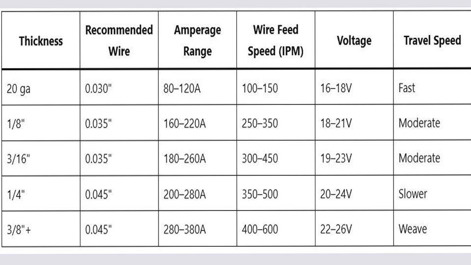
| Thickness | Recommended Wire | Amperage Range | Wire Feed Speed (IPM) | Voltage | Travel Speed |
|---|---|---|---|---|---|
| 20 ga | 0.030″ | 80–120A | 100–150 | 16–18V | Fast |
| 1/8″ | 0.035″ | 160–220A | 250–350 | 18–21V | Moderate |
| 3/16″ | 0.035″ | 180–260A | 300–450 | 19–23V | Moderate |
| 1/4″ | 0.045″ | 200–280A | 350–500 | 20–24V | Slower |
| 3/8″+ | 0.045″ | 280–380A | 400–600 | 22–26V | Weave |
Adjusting Amperage for Different Welding Positions
Gravity alters puddle control, requiring amperage shifts from flat-position baselines.
Flat and Horizontal: Baseline Settings
Use full chart amperage here—maximum deposition and easiest control. No adjustments needed beyond standard CTWD of ¾–1 inch.
Vertical Up: Increased Heat for Gravity Compensation
Add 15–25A over flat settings to keep the puddle fluid. Example: 1/4-inch plate vertical with 0.035-inch wire jumps from 200A baseline to 215–225A at 19–20V. Employ slight weave (max ¾-inch wide) and 6–8 IPM travel to avoid undercut.
Overhead: Reduced Amperage to Control Pool
Subtract 15A to prevent dripping. Overhead 1/8-inch fillet: drop from 190A to 175A while tightening stringer technique. Shorter CTWD (½ inch) helps restore effective current without raising WFS.
Self-Shielded vs. Gas-Shielded Flux Core Amperage Differences
Shielding type changes polarity, voltage, and amperage windows because external gas alters arc characteristics.
Self-Shielded (DCEN, No Gas): Outdoor and Dirty Metal
Most hobby wires (E71T-11) run DCEN with amperage 30–300A depending on diameter. Higher spatter but wind-resistant. Use 1–2V lower settings than gas-shielded; longer CTWD (up to 1¼ inches) drops effective amperage by 10–20A.
Gas-Shielded (DCEP, CO2/Argon): Cleaner Beads and Higher Voltages
Dual-shield wires (E71T-1) require DCEP and 24–34V. Amperage runs 50–70A hotter for the same WFS due to tighter arc. Example: 1/4-inch plate needs 250–320A versus 200–280A self-shielded. Cleaner slag and lower smoke make this ideal indoors for structural work.
Calculating Amperage from Wire Feed Speed Settings
On CV machines, wire feed speed (WFS) sets amperage. Approximate conversions (½-inch CTWD):
- 0.030-inch: 2–3 IPM per amp (100 IPM ≈ 40–50A)
- 0.035-inch: 1.8–2.5 IPM per amp (300 IPM ≈ 140–160A)
- 0.045-inch: 1.5–2 IPM per amp (400 IPM ≈ 220–260A)
Shorten CTWD by ¼ inch to raise amperage 10–15A without changing WFS. Test on scrap and read machine ammeter for exact values—manufacturer charts vary 5–10% by flux formulation.
Pairing Voltage with Amperage for Stable Flux Core Arcs
Voltage controls arc length and bead shape independently of amperage. Start 1V below chart maximum, then increase until the arc crackles steadily without stubbing or spatter. For 160–220A range, 18–21V keeps the puddle fluid on 1/8-inch steel.
Too low (under 17V at 200A) causes ropey beads; too high (over 23V) widens the arc and pulls nitrogen into the weld, creating porosity.
Flux Core Amperage Charts for Stainless Steel Applications
Stainless flux-cored wires (typically 0.035-inch or 0.045-inch) require 10–15% lower amperage than mild steel to control heat input and prevent carbide precipitation. For 1/8-inch stainless butt joint: 70–90A at 25–27V.
On ¼-inch fillet: 180–200A flat position. Overhead stainless drops another 10A. Use 100% CO2 or 75/25 mix; maintain short CTWD (⅝ inch) for stable arc.
Amperage Choices for Real-World Welding Projects
Automotive and Bodywork
Run 80–120A with 0.030-inch wire on 18–20-gauge panels. This prevents distortion while penetrating light rust. Vertical seams on frames add 15A for upward travel.
Structural and Trailer Fabrication
Target 220–280A with 0.045-inch wire on ¼-inch tubing or plate. Multi-pass fillets at 250A fill gaps up to ⅛-inch without preheat on clean steel.
Repair Work on Rusty Material
Self-shielded 0.035-inch at 160–200A tolerates mill scale best. Increase WFS 10% and use drag technique (10–20° angle) for deeper penetration on dirty surfaces.
Final Thoughts
Mastering amperage decisions through the flux core welding amperage chart turns variable machine output into repeatable performance. Match wire diameter to your welder’s max amps, then scale by thickness and position using the tables above.
The advanced pro-level insight: dynamically shorten CTWD by ⅛ inch on critical welds to boost effective amperage 8–12A without raising WFS, improving Charpy toughness in low-temperature structural applications while maintaining deposition rates.
FAQs
What amperage should I run for 1/4-inch mild steel with 0.035-inch flux core wire?
Use 200–280A at 350–500 IPM and 20–24V. Test on scrap and add 15A for vertical-up positions.
How does wire feed speed convert to amperage on flux core welders?
WFS controls amperage on CV machines—roughly 1.8–2.5 IPM per amp for 0.035-inch wire at standard CTWD. Shorten stickout to increase current without changing speed.
Do self-shielded and gas-shielded flux core wires use the same amperage settings?
No. Self-shielded (DCEN) runs 50–70A cooler with lower voltage; gas-shielded (DCEP) needs higher voltage and slightly more amperage for the same thickness.
What amperage range works best for beginners on 1/8-inch steel?
Start at 160–190A with 0.035-inch self-shielded wire. This window gives reliable penetration on hobby machines without burn-through risk.

Hi, I’m Zachary Ford. I’m passionate about welding and dedicated to helping both beginners and experienced welders make informed decisions. I research, test, and write about welding helmets, welding machines, safety equipment, and essential workshop tools. My goal is to provide honest reviews, practical buying guides, and easy-to-follow tutorials that help you weld more safely, work more efficiently, and choose the right gear with confidence.