Getting the parameters right in a Flux Core MIG Welding Settings Chart is critical for producing consistent, high-quality welds. Flux-cored welding relies on a precise balance of voltage, wire feed speed, and travel speed, any mismatch can lead to poor penetration, excessive spatter, unstable arc behavior, or even weld defects that fail inspection.
Unlike solid wire MIG welding, flux core introduces additional variables such as slag formation and shielding characteristics, making accurate settings even more important in real fabrication environments.
Incorrect settings don’t just affect appearance—they directly impact structural integrity, rework rates, and overall production efficiency.
A well-structured settings chart provides a reliable baseline for different material thicknesses and positions, reducing guesswork and setup time. In this guide, you’ll gain a clear understanding of how to interpret and apply these settings to improve arc stability, control heat input, and achieve consistent weld performance.
Wire Diameter Selection and Why It Dictates Your Settings
Wire diameter sets the baseline amperage range, deposition rate, and heat input you can safely apply without burn-through or lack of fusion. Thinner wire carries less current at the same WFS, producing a tighter arc suited to light gauge. Heavier wire handles higher amps and thicker plate but risks stubbing on thin material.
0.030″ Wire: Optimal for Thin to Medium Gauge Steel
Use 0.030″ E71T-GS or E71T-11 wire for 16–18 gauge up to 1/8-inch single-pass welds. At 150–250 IPM WFS it draws 60–120 amps, keeping heat low enough to avoid distortion on sheet metal.
Voltage stays in the 16–19 V range to maintain short-circuit transfer with minimal spatter. This diameter feeds smoothly on 110V machines and leaves a manageable slag blanket that chips easily after cooling.
0.035″ Wire: Balanced Choice for Most Fabrication
Switch to 0.035″ for 1/8-inch to 1/4-inch plate where you need deeper penetration without multi-pass work. At 200–350 IPM it produces 100–170 amps, delivering 20–30% higher deposition than 0.030″ while still working in all positions.
Run 17–22 V; the extra current melts thicker edges cleanly and fills gaps up to 1/16 inch. Most hobby and light industrial MIGs perform best here because the wire resists burn-back and tolerates slight wind.
0.045″ Wire: Required for Heavy Plate and High Deposition
Reserve 0.045″ for 1/4-inch and thicker where travel speed and fill rate matter. It demands 300–500 IPM and 19–25 V to reach 140–220 amps without stubbing. The larger cross-section carries more current density, making it ideal for structural fillets or groove welds but too aggressive for anything under 3/16 inch unless you drop WFS dramatically.
Polarity and Contact Tip to Work Distance (CTWD) Fundamentals
Flux core performance hinges on polarity and stickout more than voltage alone. Wrong polarity instantly collapses penetration and increases spatter.
DCEN vs DCEP – Critical for Flux Core Performance
Self-shielded flux core (E71T-GS, E71T-11, NR-211-MP) runs on DCEN (electrode negative). Reverse polarity from solid wire MIG and you lose 30–40% penetration while slag becomes unmanageable. Gas-shielded flux core (E71T-1C/M) uses DCEP; never mix the two without changing wire.
Confirm your machine’s polarity switch before striking an arc—DCEN produces the hotter arc needed for the flux to generate its own shielding.
Optimal Stickout Lengths by Wire Size and Thickness
Maintain ½–¾ inch CTWD for 0.030″ and 0.035″ wire; extend to ¾–1¼ inch for 0.045″ on thick plate. Longer stickout on self-shielded wire preheats the flux core, improving slag fluidity and reducing porosity in windy conditions.
Too short and you starve the flux of space to react; too long and voltage drops, causing poor fusion. Measure from contact tip to plate, not gun nozzle.
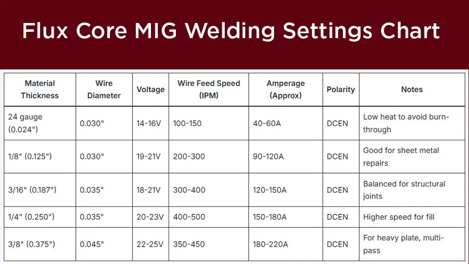
Comprehensive Flux Core MIG Welding Settings Chart
The table below compiles manufacturer-derived starting points for self-shielded flux core on mild steel (flat position, single pass). All values assume DCEN, clean metal, and ¾-inch CTWD. Fine-tune ±1–2 V or 20–30 IPM after test beads.
| Material Thickness | Wire Diameter | Voltage (V) | Wire Feed Speed (IPM) | Approx. Amps | Travel Speed (IPM) | Notes |
|---|---|---|---|---|---|---|
| 16–18 ga (thin sheet) | 0.030″ | 16–18 | 150–220 | 60–100 | 10–15 | Stringer beads; low heat to prevent burn-through |
| 1/8″ (3.2 mm) | 0.030″ or 0.035″ | 17–20 | 200–300 | 90–140 | 8–12 | Fillets or butt joints; watch for undercut on edges |
| 3/16″ (4.8 mm) | 0.035″ | 18–22 | 250–350 | 120–170 | 6–10 | Multi-pass if gap >1/16″; preheat if cold |
| 1/4″ (6.4 mm) | 0.035″ or 0.045″ | 19–23 | 300–420 | 140–200 | 5–8 | Strong root pass; chip slag between layers |
| 3/8″ (9.5 mm) | 0.045″ | 20–24 | 350–480 | 160–220 | 4–7 | Weave or multi-pass; 200°F preheat recommended |
| 1/2″ and thicker | 0.045″ | 21–25 | 400–500+ | 180–240 | 3–6 | Groove prep required; high-duty-cycle machine needed |
Test every new spool or machine on scrap. Arc should sound like steady frying bacon—crackly but consistent.
Adjusting Parameters for Welding Positions
Position changes heat input requirements because gravity affects puddle control.
Flat and Horizontal: Maximum Deposition Settings
Flat position lets you run the high end of the chart (max WFS and voltage) for fastest travel and highest deposition. Use a 10–15° push angle to keep slag behind the puddle.
Vertical Up: Reducing Heat Input to Control the Pool
Drop voltage 1–2 V and WFS 10–20% from flat settings. Shorten stickout to ½ inch and use a slight weave with pauses at the toes. This prevents sagging while maintaining fusion on 3/16-inch and thicker vertical fillets.
Overhead: Short Stickout and Faster Travel
Overhead demands the lowest heat input—reduce WFS another 10% and keep travel speed high. Maintain ½-inch stickout max and a tight 5–10° drag angle. Slag flows downward naturally; any pause risks dripping.
Gas-Shielded Flux Core vs Self-Shielded: Parameter Differences
Self-shielded dominates portable work, but gas-shielded (FCAW-G) offers cleaner beads indoors.
When to Switch to Gas for Cleaner Beads
Use 75% Ar/25% CO2 or straight CO2 with E71T-1C/M wire when appearance and low spatter matter more than wind resistance. Gas versions run DCEP and require 1–2 V higher settings plus shorter stickout (⅜–⅝ inch).
Voltage and WFS Shifts with CO2 or Mixed Gas
Gas-shielded typically needs 18–26 V and 10–15% higher WFS than self-shielded equivalents for the same thickness because the external shield allows tighter arc control. Penetration increases but slag volume drops dramatically. Never run gas-shielded wire without gas—porosity is guaranteed.
Fine-Tuning Settings Based on Arc Sound and Bead Appearance
Voltage primarily controls arc length and bead width; WFS controls amperage and penetration.
Diagnosing and Correcting Voltage Issues
Too high voltage (>chart max) produces a long, hissing arc with excessive spatter and concave beads. Drop 1 V increments until the arc tightens and spatter falls. Too low voltage creates a stubby arc that pops and leaves convex beads with poor tie-in—raise voltage until the puddle flows.
Wire Feed Speed Adjustments for Penetration Control
Increase WFS to add heat and penetration without changing voltage much. On thick plate, higher WFS fills faster but risks burn-through on thin edges; reduce it 30–50 IPM when fit-up is poor.
Monitor your machine’s ammeter if equipped—target 1 amp per 0.001 inch of thickness as a rough check, adjusted upward 20% for flux core.
Machine-Specific Considerations for Flux Core Settings
110V vs 220V Welders – Output Limits
110V machines top out around 140–160 amps continuous, so stay with 0.030″ or 0.035″ wire and shorter runs. 220V units handle 0.045″ at full chart values and sustain higher duty cycles for production work.
Synergic vs Manual Mode Parameter Mapping
Synergic modes pre-map voltage to WFS for flux core—select the “gasless” or “flux” program and trim ±10% based on test beads. Manual mode gives full control but requires you to reference the chart above and ignore solid-wire presets.
Performance-based Takeaway
Matching voltage, WFS, polarity, and stickout to the exact wire and thickness in the Flux Core MIG Welding Settings Chart above consistently delivers X-ray quality penetration with minimal cleanup. The next time you face windy outdoor fabrication or tight shop deadlines, these parameters let you skip trial-and-error and focus on joint design instead.
Master one advanced insight: on ¼-inch and thicker plate, run the root pass 1–2 V hotter than fill passes to achieve full penetration, then drop voltage on cap passes for a flat, low-profile bead that needs almost no grinding—exactly how structural shops achieve 30% faster production while staying code-compliant.

Hi, I’m Zachary Ford. I’m passionate about welding and dedicated to helping both beginners and experienced welders make informed decisions. I research, test, and write about welding helmets, welding machines, safety equipment, and essential workshop tools. My goal is to provide honest reviews, practical buying guides, and easy-to-follow tutorials that help you weld more safely, work more efficiently, and choose the right gear with confidence.