Flux-cored arc welding (FCAW) is widely used for its strong penetration and ability to handle less-than-clean metal, but one common question still causes confusion: does flux core welding require gas ? The answer directly impacts weld quality, equipment setup, and operating cost.
Choosing the wrong configuration can lead to poor arc stability, excess spatter, lack of fusion, or unnecessary shielding expenses.
In practice, flux core wire comes in two types—self-shielded and gas-shielded—and each behaves differently under real welding conditions. Understanding when shielding gas is required, and when it isn’t, is critical for maintaining proper bead profile, minimizing defects, and ensuring structural
I’ll clarifies the role of shielding gas in flux core welding, helping you make the correct setup decision based on material, environment, and performance requirements.
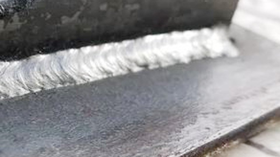
Image by reddit
Self-Shielded Flux Core Welding: Gas-Free Operation in Demanding Conditions
Self-shielded flux core wires rely entirely on internal flux ingredients that decompose in the arc to produce shielding gases and slag. No external cylinder or regulator is needed.
The process uses aluminum and other deoxidizers in the core to react with atmospheric oxygen and nitrogen, forming compounds trapped in the slag rather than the weld metal. This makes FCAW-S the default for field work where dragging a gas bottle is impractical.
Polarity, Arc Transfer, and Deposition Behavior
Run self-shielded wires on DCEN (electrode negative). This concentrates heat at the workpiece for deeper penetration while the electrode melts faster, supporting higher wire feed speeds without burn-back.
Globular transfer dominates—larger droplets create a harsher arc than gas-shielded counterparts, but deposition rates still reach 4–9 lb/hr with 0.045-inch wire at 180–250 A on flat plate. Real-world stickout stays at ½–¾ inch; exceeding 1 inch risks unstable arcs and worm-tracking.
Material Thickness and Contaminant Tolerance
FCAW-S excels on material ⅛ inch and thicker, especially with rust, mill scale, or light oil. The flux chemistry tolerates surface impurities that would cause porosity in solid-wire MIG. Use 0.035-inch wire for ⅛–¼ inch steel at 160–210 A and 23–25 V; step up to 0.045-inch for ¼–½ inch plate at 200–280 A.
In vertical-up or overhead positions, drop amperage 15–20% and shorten stickout to maintain puddle control. Outdoor wind has zero effect on shielding, unlike gas processes.
Trade-Offs in Bead Appearance and Cleanup
Expect heavier slag coverage and higher spatter than gas-shielded wires. Slag removes easily in most formulations but requires chipping or grinding between multi-pass layers to avoid inclusions.
Deposition efficiency sits around 70% because some filler metal forms the shielding gas itself. These realities suit structural work or repairs where speed and portability outweigh cosmetic perfection.
Gas-Shielded Flux Core Welding: External Gas for Precision and Efficiency
Gas-shielded wires combine internal flux with an external shielding gas for dual protection. The gas blanket reduces atmospheric contamination while the flux handles deoxidation and alloying. FCAW-G delivers smoother arcs, lower spatter, and easier slag removal—ideal when you already have gas infrastructure.
Shielding Gas Selection and AWS Classifications
Match the wire to the gas. E71T-1C wires require 100% CO₂ for deeper penetration but produce more spatter. E71T-1M wires use 75% argon/25% CO₂ for reduced spatter and smoother beads. Dual-classified wires (C/M) run on either.
Flow rates of 35–45 CFH keep the puddle protected indoors; drop to 30 CFH minimum in low-draft areas. CO₂ costs less but increases cleanup time; argon mixes raise gas expense yet cut post-weld grinding by 30–50%.
Polarity and Spray-Like Transfer Advantages
FCAW-G runs on DCEP (electrode positive). Heat focuses on the wire tip, producing smaller droplets and a spray-like transfer that improves operator appeal and bead wetting. Arc stability increases, allowing consistent travel speeds of 12–18 IPM on ¼-inch plate. Deposition efficiency climbs to the mid-80% range because the external gas handles most shielding duties.
Shop Applications and All-Position Performance
Gas-shielded wires shine in controlled environments—structural steel, shipyards, or heavy fabrication—where windshields or enclosures protect the gas shield. They support higher deposition on thicker sections and excel in vertical-up or overhead work because the slag freezes faster than the weld pool, creating a natural shelf.
For 0.045-inch E71T-1M wire on ⅜-inch plate, settings of 220–280 A, 25–28 V, and 75/25 gas yield radiographic-quality welds with minimal defects.
Direct Performance Comparison: Self-Shielded vs. Gas-Shielded Flux Core
| Factor | Self-Shielded (FCAW-S) | Gas-Shielded (FCAW-G) |
|---|---|---|
| External Gas Required | No | Yes (CO₂ or Ar/CO₂) |
| Polarity | DCEN | DCEP |
| Typical Spatter | Higher | 30–50% lower |
| Slag Removal | Moderate effort | Easier, faster |
| Outdoor/Windy Use | Excellent | Requires wind protection |
| Deposition Efficiency | ~70% | Mid-80%+ |
| Best Material Range | ⅛ inch and thicker, dirty surfaces | Clean surfaces, all positions |
| Portability | Highest | Limited by cylinder |
These numbers come from direct side-by-side testing on mild steel; actual results shift with wire diameter, machine calibration, and joint prep.
Optimizing Machine Settings for Reliable Flux Core Welds
Correct parameters prevent 90% of common defects. Use constant-voltage (CV) output. Knurled drive rolls grip the softer flux-cored wire without crushing the core; tension should allow smooth feeding without slippage or bird-nesting.
Wire Diameter and Amperage Guidelines
For 0.035-inch self-shielded wire on ¼-inch butt joints: 200–210 A, 24–25 V, 400–420 IPM wire feed, DCEN. Gas-shielded equivalent on the same joint: 210–220 A, 25–26 V, 220–240 IPM, DCEP, 75/25 gas. Scale down 10–15% for vertical positions. Preheat material thicker than ½ inch to 150°F to avoid hydrogen cracking.
Stickout, Voltage, and Travel Speed
Maintain ½–¾ inch contact-tip-to-work distance. Longer stickout on self-shielded wires increases resistive heating and deposition but risks instability.
Voltage directly controls arc length—too low causes stubbing; too high creates excessive spatter. Travel speed must keep the puddle ahead of the slag; rushing produces cold laps, while lingering invites burn-through on thin stock.
Gas Flow and Regulator Setup for FCAW-G
Set the flowmeter to 35–45 CFH at the torch. Check for leaks at hose fittings and the gun diffuser. In drafty shops, add a gas lens or nozzle extension. Never run gas-shielded wire without gas—porosity appears instantly as scattered holes visible after slag removal.
Environmental and Project Factors That Decide Your Shielding Choice
Outdoor structural repairs or agricultural equipment fixes almost always favor self-shielded wire. Indoor shop work on clean plate where appearance and X-ray quality matter pushes toward gas-shielded. For ⅛-inch auto body panels, gas-shielded with argon mix minimizes distortion and post-weld grinding.
On contaminated farm equipment outdoors, self-shielded handles mill scale without pre-cleaning. All-position work on pressure vessels benefits from gas-shielded slag control; flat-position fillet welds on thick plate run faster gasless.
Troubleshooting Shielding-Related Defects in Flux Core Welding
Porosity signals lost shielding. On self-shielded wire, check for moisture in the spool or excessive stickout. On gas-shielded, verify flow rate, leaks, or wind interference. Excessive spatter usually traces to incorrect polarity or voltage mismatch—swap polarity and drop voltage 1–2 V.
Slag inclusions appear from travel speed too slow or inadequate inter-pass cleaning. Worm tracks (longitudinal grooves) result from excessive stickout or low voltage; shorten stickout and raise voltage slightly.
Final Thoughts
Choosing the right flux core variant—gasless for mobility and wind resistance or gas-assisted for cleanliness and speed—directly determines whether your welds pass inspection on the first try or require rework.
Real-world welders who match wire type, polarity, gas (or lack of it), and parameters to the exact job achieve deposition rates above 10 lb/hr on heavy plate while maintaining radiographic quality.
The next level comes from recognizing that dual-shielded techniques (gas plus optimized flux) on high-strength low-alloy steels let you push travel speeds 20% higher without sacrificing fusion—turning a good welder into the one whose joints never fail under load.
Frequently Asked Questions
What gas works best with gas-shielded flux core wire?
Use 100% CO₂ for E71T-1C wires when maximum penetration is needed and cleanup time is acceptable. Switch to 75% argon/25% CO₂ for E71T-1M wires to cut spatter and improve bead appearance. Dual-classified wires give flexibility—test both on scrap to match your priorities.
Can you run flux core wire in a standard MIG welder without gas?
Yes—if the wire is self-shielded. Flip polarity to DCEN, remove or cap the gas nozzle if desired, and use knurled drive rolls. Gas-shielded wire will produce immediate porosity without external gas.
Is flux core welding stronger with gas or without?
Strength depends on filler metal chemistry and proper parameters, not gas alone. Both processes meet the same AWS tensile requirements when classified correctly. Gas-shielded often yields cleaner, more consistent mechanical properties in multi-pass welds due to reduced porosity risk.
How do you convert a MIG machine for flux core use?
Install knurled drive rolls sized for your wire diameter, set polarity correctly (DCEN for most self-shielded, DCEP for gas-shielded), and adjust voltage and wire speed per manufacturer charts. Test on scrap to dial in arc stability before production.

Hi, I’m Zachary Ford. I’m passionate about welding and dedicated to helping both beginners and experienced welders make informed decisions. I research, test, and write about welding helmets, welding machines, safety equipment, and essential workshop tools. My goal is to provide honest reviews, practical buying guides, and easy-to-follow tutorials that help you weld more safely, work more efficiently, and choose the right gear with confidence.