Many welders face uncertainty when sizing fillet welds for brackets, frames, or structural joints. A weld that looks strong on the surface may fail under shear or combined loading if the throat dimension, electrode strength, and load direction are miscalculated.
Learning how to calculate fillet weld strength ensures the joint carries the intended load without over-welding (which wastes time and material) or under-welding (which risks failure).
Accurate calculations balance safety, cost, and performance across DIY projects, student assignments, and professional fabrication.
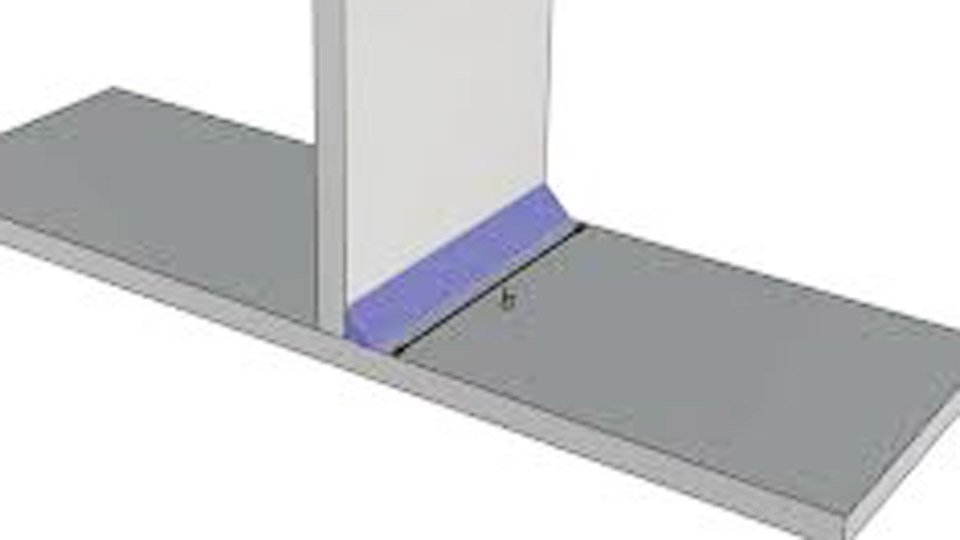
Image by structuralbasics
Understanding Fillet Weld Geometry and Effective Throat
Fillet welds form a triangular cross-section joining two surfaces, typically at 90 degrees. The leg length (z or s) is the distance from the root to the toe along each plate. The critical dimension for strength is the effective throat (a or t_e), the shortest distance from the root to the weld face.
For a standard equal-leg fillet weld at 90°, the theoretical throat equals leg length × 0.707 (sin 45°). This assumes a flat or slightly convex face with full root fusion. Convexity adds minor extra metal but codes ignore it for conservative design. Concavity reduces effective throat and requires adjustment.
Unequal leg fillets or welds on angled joints need trigonometric adjustment. For a leg on the horizontal plate of length a and vertical of length b, calculate the throat using the perpendicular distance from root to hypotenuse.
Deep penetration processes (e.g., submerged arc or high-current GMAW) can increase actual throat beyond the theoretical value, but most hand calculations use the standard 0.707 factor unless qualified by testing or WPS.
Effective length excludes the start and stop craters (typically 2× weld size at each end for continuous welds) and any unwelded portions. Codes like AWS D1.1 specify minimum effective lengths to avoid stress concentrations.
Key Formulas for Fillet Weld Strength Calculation
Strength depends on the effective throat area and the allowable or design stress of the weld metal. In allowable stress design (ASD, common in the US via AISC/AWS), allowable shear stress on the throat is typically 0.30 × F_EXX, where F_EXX is the electrode’s minimum tensile strength in ksi.
For a transverse or longitudinal shear load parallel to the weld axis:
Allowable load (P) = 0.707 × leg size (in) × length (in) × 0.30 × F_EXX (ksi) × 1000 (to convert to pounds)
A common rule-of-thumb for E70XX electrodes (F_EXX = 70 ksi): capacity ≈ 0.928 kips per inch of length per 1/16″ of leg size. Thus, a 1/4″ (4/16″) fillet carries about 3.71 kips per inch of effective length in shear.
In Load and Resistance Factor Design (LRFD):
Nominal strength R_n = 0.60 × F_EXX × effective area (A_w), with resistance factor φ = 0.75 for fillet welds in shear.
Effective area A_w = effective throat × effective length.
Eurocode EN 1993-1-8 uses a simplified method: design resistance per unit length = f_u × a / (√3 × β_w × γ_M2), where β_w is a correlation factor (often 0.8–1.0 depending on steel grade) and γ_M2 = 1.25. The directional method accounts for normal and shear stress components separately with a more complex von Mises-like check.
Always compare weld strength to base metal capacity. The weld should not exceed the strength of the thinner plate in shear or tension to avoid base metal failure.
Load Direction and Directional Strength Increase
Fillet welds loaded longitudinally (parallel to the weld axis) experience pure shear on the throat. Transverse loading (perpendicular to the axis) increases strength by up to 50% due to the combined stress state and failure plane shifting.
AWS D1.1 and AISC permit a directional strength increase factor of (1.0 + 0.50 sin^{1.5} θ), where θ is the angle between load direction and weld axis (0° longitudinal, 90° transverse). At 90°, this reaches 1.5.
This increase applies mainly to static loading; fatigue applications often ignore or limit it. For combined loads (e.g., bracket with vertical shear and horizontal tension), resolve forces into components parallel and perpendicular to each weld segment, then vectorially combine stresses on the throat.
In torsion or eccentric loading, calculate the center of gravity of the weld group, determine primary shear (direct force/area), and secondary shear from moment (M × distance / polar moment of inertia of the weld group treated as lines with unit throat). The resultant shear stress must stay below allowable.
Electrode Selection and Weld Metal Properties
Choose electrodes that match or slightly undermatch the base metal for fillet welds (AWS D1.1 allows undermatched for fillets only). Common classifications:
- E60XX: F_EXX = 60 ksi → allowable shear ≈ 18 ksi on throat
- E70XX: 70 ksi → allowable shear ≈ 21 ksi
- E80XX or higher for higher-strength steels
Hydrogen-controlled low-hydrogen electrodes (e.g., E7018) reduce cracking risk in thicker materials or restrained joints. Flux-cored (FCAW) or metal-cored wires offer higher deposition but may require different strength adjustments per manufacturer data.
Weld metal strength governs when it is lower than base metal. For A36 steel (Fu ≈ 58–80 ksi), E70XX is standard. Overmatching provides little extra capacity in fillet welds under current codes, unlike groove welds.
Minimum and Maximum Fillet Weld Sizes
Codes impose minimum sizes to ensure adequate heat input and prevent rapid cooling that causes hydrogen cracking or brittle HAZ.
Per AWS D1.1 Table 7.7 (or AISC J2.4):
- Base metal < 1/4″ thick: min 1/8″ leg
- 1/4″ to 1/2″: min 3/16″
- 1/2″ to 3/4″: min 1/4″
- Over 3/4″: min 5/16″
For cyclically loaded structures, minimum often increases to 3/16″.
Maximum size along edges: usually thickness of thinner part minus 1/16″ for plates ≥1/4″ to allow visual inspection of the toe. On thinner material, max leg cannot exceed plate thickness.
Intermittent fillets require minimum length (typically 4× size) and maximum spacing (e.g., 12″ or 24× thickness) depending on load type.
Practical Calculation Examples
Example 1: Longitudinal Shear on a Lap Joint
A bracket with 10,000 lb vertical shear uses two 6″ long fillet welds on each side of a 1/4″ plate (E70XX electrode). Required leg size?
Effective throat per weld = 0.707 × leg. Total area for two welds (one side considered, but typically double-sided) = 2 × length × throat.
Using simplified: capacity per inch per 1/16″ leg ≈ 0.928 kips (E70).
For 10 kips total, assume two welds sharing load: 5 kips each.
Leg size (in 1/16ths) = 5 / (6 × 0.928) ≈ 0.90 → use 1″ or 1/16″ wait, recalculate properly: 5 kips / (6 in × 0.928 k/in per 1/16) ≈ 0.90 sixteenths? No:
0.928 kips per inch length per 1/16″ leg. For 6″ length: 6 × 0.928 = 5.568 kips capacity per 1/16″ leg.
For 5 kips: leg ≈ 5 / 5.568 ≈ 0.9 sixteenths → 1/16″ is marginal; calculate exactly with 0.707 factor.
Standard: allowable load = leg (in) × 0.707 × length × 21 ksi (0.3×70).
Leg = 5000 / (0.707 × 6 × 21000) ≈ 5000 / 89082 ≈ 0.056″ → but apply min size 3/16″ for 1/4″ plate. Real designs use min or check actual.
Adjust for two sides or correct sharing.
Example 2: Transverse Fillet with Directional Increase
Same load but transverse: apply 1.5 factor or use formula. Capacity rises significantly, allowing smaller legs or shorter lengths.
Combined Loading Example
For an eccentric bracket, compute vector sum of primary shear (V/A) and torsional shear (T r / J), where J is polar inertia of weld group (treat welds as lines: I_xx, I_yy, J = I_xx + I_yy).
Resultant τ ≤ allowable.
These calculations often require spreadsheets or software for complex groups, but hand methods using weld group properties (from Blodgett or AISC tables) work for common patterns like C-shaped or angle connections.
Base Metal Considerations and Joint Efficiency
Weld strength must not govern if base metal is weaker. For A36 plate, shear capacity of base ≈ 0.6 × Fu × plate area (gross or net).
In lap joints, check for shear lag or block shear. Thinner plate thickness limits maximum practical fillet size.
Fit-up gaps >1/16″ reduce effective throat; codes limit gaps or require larger welds.
When to Use Advanced Methods or Testing
For critical applications (pressure vessels, bridges, seismic), qualify WPS with procedure tests measuring actual strength. Macro-etch samples verify penetration.
Finite element analysis helps with complex stress distributions, but most shop calculations stay with code formulas.
Fatigue reduces allowable stress dramatically; use AWS D1.1 fatigue categories or Eurocode detail classes. Fillet welds in tension transverse to load have poorer fatigue performance than longitudinal.
Choosing Between Fillet and Groove Welds
Fillet welds suit T- or lap joints with lower preparation. Groove welds (CJP or PJP) provide higher strength for butt joints or when full penetration is needed, but require beveling, more passes, and inspection.
Transition when fillet size would exceed ~3/4 of thinner plate thickness or when loads demand it. Hybrid connections sometimes combine both.
Real-World Decision Factors
Process and position: SMAW in vertical/overhead may need larger legs for same deposition. GMAW/FCAW allow faster travel and better penetration.
Material thickness and restraint: Thicker or highly restrained joints need low-hydrogen processes and possibly preheat.
Inspection level: Visual, dye penetrant, or UT affects acceptance and required oversizing.
Cost: Larger welds increase filler metal, time, and distortion. Optimize length and size rather than defaulting to continuous oversized welds.
Use tables from AISC Manual or Blodgett’s Design of Welded Structures for quick allowable loads by size and electrode.
Decision-Making Summary for Fillet Weld Strength
To calculate fillet weld strength correctly, always start with effective throat (0.707 × leg for equal 90° fillets), multiply by length and allowable shear stress (0.30 F_EXX in ASD), then adjust for load angle, eccentricity, and code-specific factors. Verify against base metal capacity and minimum size requirements.
For transverse loads, leverage the directional increase where permitted. Complex cases demand vector analysis of the full weld group.
A pro-level insight: the actual failure plane in transversely loaded fillets often sits near 22.5° rather than the theoretical 45° throat, explaining why tested strengths exceed simple shear predictions—yet conservative code formulas keep structures safe across variables like penetration consistency and residual stresses. Apply these calculations on your next project to size welds that perform reliably without excess.
FAQs
What is the formula for fillet weld strength in shear?
Allowable capacity (ASD) = 0.707 × leg size (in) × effective length (in) × 0.30 × F_EXX (ksi) × 1000 lb/kip. Use throat area directly for precision.
Does load direction affect fillet weld strength?
Yes. Longitudinal shear uses base allowable; transverse loading allows up to 1.5× increase per AISC/AWS directional factor due to improved stress distribution.
How do I determine minimum fillet weld size?
Follow AWS D1.1 or AISC Table J2.4 based on thinner base metal thickness. For 1/4″–1/2″ plate, minimum is typically 3/16″. Never undersize below this for structural work.
Can I use undermatched electrodes for fillet welds?
AWS D1.1 permits it for fillets (strength based on electrode), unlike groove welds. Match or slightly undermatch common for economy when base metal allows. Always confirm with project specs.