Determining weld size is a critical step in ensuring joint strength, load capacity, and long-term performance. How to Determine Proper Weld Size is not just a calculation, it directly affects penetration, heat input, and the weld’s ability to withstand service stresses.
An undersized weld can lead to premature failure, lack of fusion, or cracking, while an oversized weld increases distortion, material cost, and unnecessary heat input.
Proper weld sizing depends on factors such as base metal thickness, joint configuration, welding process, and applicable codes or standards. Misjudging any of these can result in inspection failures or costly rework. In real fabrication environments, achieving the correct balance between strength and efficiency is essential for both structural integrity and productivity.
This guide clarifies the key principles and practical methods used to determine accurate weld size, helping you produce welds that meet design requirements without overbuilding or risking failure.
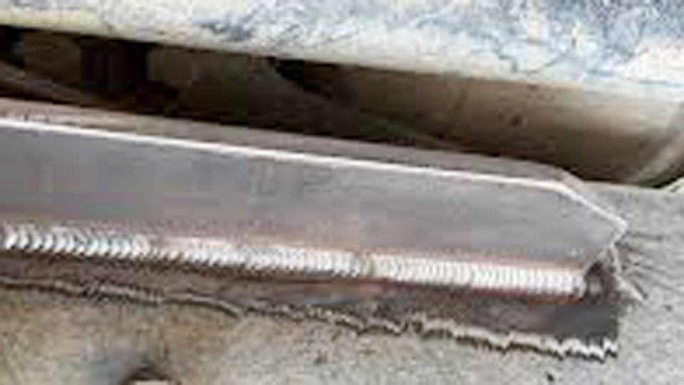
Image by structolution
Understanding Weld Size Fundamentals
Weld size definitions vary by joint type, yet every decision starts with the geometry that governs strength calculations. Fillet welds rely on leg length and throat dimensions, while groove welds depend on penetration depth. These measurements translate directly into effective load-bearing area.
Leg Size Versus Throat Size in Fillet Welds
Fillet weld size is defined by the leg length—the length of the two sides forming the right triangle inscribed in the weld cross-section. The theoretical throat equals leg length multiplied by 0.707 for a 45-degree isosceles fillet. In practice, the effective throat accounts for actual fusion and any convexity or concavity permitted by code.
For example, a 1/4-inch leg produces a theoretical throat of approximately 0.177 inches. Strength calculations always use the throat because failure occurs along the shortest failure plane through the weld metal. AWS D1.1 measures size exclusively by the leg; throat verification confirms profile compliance but does not replace leg sizing on drawings.
Effective Weld Size in Groove Welds
Groove welds use effective size as the minimum distance from the weld root to the face, minus any required deduction for incomplete penetration in partial joint penetration (PJP) details.
Complete joint penetration (CJP) groove welds achieve full base-metal thickness as effective size when matching filler metal is used, making joint strength equal to the base metal.
PJP grooves specify effective throat directly on the welding symbol, often as the depth of bevel minus 1/8 inch in certain codes to account for root imperfections. This distinction drives decisions when full penetration is impractical due to access or distortion limits.
Code-Mandated Minimum Weld Sizes
AWS D1.1 establishes absolute floor values for fillet weld leg size to guarantee adequate heat input and fusion. These minima override designer calculations when loads would otherwise permit smaller welds.
AWS D1.1 Minimum Fillet Weld Size Table
The table below lists minimum fillet weld sizes based on the thickness of the thinner part joined when using low-hydrogen processes. For non-low-hydrogen processes without qualified preheat, use the thicker part thickness.
| Base Metal Thickness (T) | Minimum Fillet Weld Size |
|---|---|
| T < 1/4 in (T < 6 mm) | 1/8 in (3 mm) |
| 1/4 in ≤ T ≤ 1/2 in (6–12 mm) | 3/16 in (5 mm) |
| 1/2 in < T ≤ 3/4 in (12–20 mm) | 1/4 in (6 mm) |
| T > 3/4 in (T > 20 mm) | 5/16 in (8 mm) |
Notes: Weld size need not exceed the thickness of the thinner part joined. For cyclically loaded structures, the minimum increases to 3/16 in (5 mm) regardless of thickness. Single-pass execution is required for non-low-hydrogen processes to maintain heat input.
Why Minimum Sizes Prevent Cracking
These requirements stem from metallurgical necessity. Small welds on thicker plate deliver insufficient heat input, producing rapid cooling rates that form brittle martensite in the heat-affected zone. Hydrogen-induced cracking follows unless preheat or low-hydrogen consumables are used.
The minima ensure single-pass heat input stays high enough for controlled cooling even on 1/4-inch material. Overriding them requires engineer approval and procedure qualification.
Adjustments for Cyclic Loading and Dissimilar Thicknesses
Cyclically loaded joints demand the 3/16-inch floor to resist fatigue crack initiation at the weld toe. When joining plates of unequal thickness, the thinner plate governs the minimum unless non-low-hydrogen processes apply.
Aluminum structures under AWS D1.2 follow similar logic but allow greater convexity tolerance and do not penalize slight oversizing.
Load-Based Weld Size Calculations
Code minima provide the floor, but actual loads often dictate larger sizes. Calculations use throat area and allowable stresses from AWS D1.1 or AISC 360.
Fillet Weld Strength Under Shear Loading
The nominal shear strength of a fillet weld equals 0.60 × F_EXX × effective throat area, where F_EXX is the electrode tensile strength. For a 70-ksi electrode (E70), this yields 42 ksi on the throat. Required leg size derives from rearranging: leg = (required load per inch) / (0.707 × 0.60 × F_EXX).
Example: A lap joint carries 12 kips per inch of weld length using E70 electrodes. Required throat = 12 / 42 = 0.286 in. Required leg = 0.286 / 0.707 ≈ 0.404 in (use 7/16 in). LRFD applies a resistance factor of 0.75; ASD uses allowable stress of 0.30 × F_EXX.
Tension and Combined Loading Considerations
Transverse-loaded fillets develop higher capacity than longitudinal ones due to throat orientation. Combined shear and tension require vector analysis of stresses on the throat plane. The interaction equation checks √(σ² + 3τ²) ≤ allowable.
Designers select leg size that satisfies both directional components simultaneously. In practice, most shop calculations default to the conservative longitudinal shear value unless detailed finite-element analysis justifies otherwise.
Using AISC Formulas for Real-World Joints
AISC Table J2.5 provides directional strength increase factors for transversely loaded welds up to 1.5 times longitudinal capacity. For eccentric bracket connections, instantaneous center of rotation methods or simplified tables yield effective weld length reductions.
Software or pre-calculated tables speed decisions, but manual verification against the governing load case remains mandatory before releasing drawings.
Specifying Weld Size on Drawings and Symbols
Welding symbols eliminate ambiguity by placing size, length, and pitch in precise locations relative to the reference line.
Fillet Weld Symbol Dimensions
Leg size appears to the left of the fillet symbol. Unequal legs use two dimensions separated by a slash or note indicating orientation. Length follows to the right; intermittent welds add pitch after a dash.
No dimension means the weld runs the full joint length. AWS A2.4 governs placement: arrow-side versus other-side welds flip symbol position accordingly.
Groove Weld Size Notation and Penetration Requirements
Groove symbols list depth of bevel followed by effective weld size in parentheses when PJP. CJP symbols omit size entirely or state “CJP.” Root opening, groove angle, and backing requirements occupy the tail. Effective size for PJP equals minimum specified throat; any shortfall triggers rejection during inspection.
Verifying and Measuring Weld Size Onsite
Field checks confirm shop execution matches design intent using standardized gauges and acceptance tables.
📏 Essential Tools for Determining Proper Weld Size
Accurate weld sizing starts with proper measurement, fit-up, and visibility. These tools can help you verify weld dimensions and produce stronger, code-compliant welds.
Welding Fillet Gage 8-Piece Set
Measure fillet weld leg size and throat dimensions accurately for fabrication and inspection work.
Check Price on Amazon →Strong Hand Tools Magnetic V-Pads Kit
Maintain accurate joint alignment before welding to help achieve consistent weld sizing and fit-up.
Check Price on Amazon →Auto-Darkening True Color Welding Helmet
Improve visibility and weld control with a large-view true-color welding helmet for consistent weld quality.
Check Price on Amazon →Tools for Accurate Leg and Throat Measurement
Multipurpose fillet weld gauges measure both legs and theoretical throat in a single placement. Convexity or concavity readings come from the same tool set. Digital calipers supplement for groove depth verification. Measure at least every 12 inches along the weld length and at ends, averaging multiple points to account for variation.
Accounting for Convexity Limits per AWS Tables
AWS D1.1 Table 7.9 limits convexity based on weld width. For a 1/4-inch leg fillet, maximum convexity is typically 1/16 inch. Excess convexity reduces effective throat and creates stress risers at the toes.
Inspectors subtract allowable convexity from measured leg when calculating effective throat for acceptance. Concave profiles require throat measurement to confirm minimum size.
Advanced Factors Affecting Weld Size Decisions
Material strength, joint geometry, and service conditions refine final sizing beyond basic calculations.
Material Properties and Matching Filler Metal
Base metal yield strength must be matched or exceeded by weld metal for full-capacity joints. Overmatching filler allows smaller welds in some tension applications but is restricted in fatigue-critical members. Aluminum alloys under D1.2 require filler selection that maintains corrosion resistance without compromising throat strength.
Joint Configuration and Access Limitations
T-joints, corner joints, and tubular connections alter effective throat orientation and available welding positions. Restricted access may force larger single-pass sizes to achieve fusion without multiple starts and stops. Distortion control often favors balanced double-sided fillets over oversized single-sided welds.
Process Efficiency and Distortion Control
Higher-deposition processes like FCAW permit larger single-pass fillets, reducing total heat input compared with multiple SMAW passes. Travel speed and technique directly influence convexity; experienced operators maintain flat profiles that maximize throat efficiency without post-weld grinding.
Performance-based Takeaway
Start every weld size decision with the AWS D1.1 minimum table, scale upward using throat-area calculations for the governing load case, and verify both symbol notation and field measurements against convexity limits. This sequence delivers code-compliant joints that carry design loads at the lowest possible fabrication cost.
In fatigue-critical structures, the advanced insight is that toe radius and effective throat profile often govern life more than raw leg size, specifying 1/16-inch larger fillets or post-weld toe grinding can double fatigue resistance without increasing overall weld volume.