Building a reliable welding power source is a practical challenge when cost, availability, or specific amperage needs limit access to commercial units. Understanding how to make arc welding machine at home is primarily a technical task—one that directly affects arc stability, current control, and weld penetration.
A poorly configured machine can lead to inconsistent arcs, weak fusion, excessive spatter, or even electrode sticking, all of which compromise weld integrity and increase rework.
For fabricators and DIY welders, the ability to assemble a functional arc welder isn’t just about saving money—it’s about controlling output characteristics to match real welding conditions. Transformer selection, voltage regulation, and current delivery must align to produce a stable arc under load.
This guide focuses on the essential principles and practical considerations required to build a safe, usable arc welding machine that performs consistently in real-world fabrication scenarios.
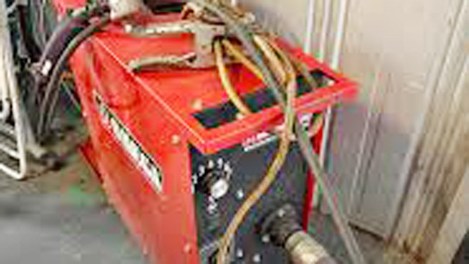
Image by fb
Assessing Your Needs: Matching Output to Actual Home Welding Tasks
Before cutting the first wire, define the target amperage and voltage window that matches the jobs you actually perform. Most garage repairs fall between 80 A and 180 A. Thin sheet (1–3 mm) runs comfortably at 80–120 A with 1/16-inch rods.
Frame work and 1/4-inch plate need 140–180 A with 3/32-inch or 1/8-inch electrodes. Exceeding 200 A continuously on a pair of MOTs pushes the primary side near breaker limits on a standard 220 V 20 A household circuit.
Amperage and material thickness decision matrix
- 80–120 A: 1–3 mm mild steel, 1/16-inch 6013 rods
- 120–160 A: 3–5 mm plate, 3/32-inch rods
- 160–200 A: 5–8 mm sections, 1/8-inch rods (short runs only)
OCV must sit between 35 V and 50 V AC for reliable arc initiation. Below 30 V the arc starts hard and extinguishes easily. Above 60 V the machine becomes unnecessarily hazardous on exposed terminals. These numbers come directly from the turns ratio and core saturation limits of typical MOTs.
AC versus DC output considerations
Standard MOT builds deliver AC. Most 6013 and 7018 rods tolerate AC without major issues, though DC provides smoother starts and less spatter on thin material. Adding a full-wave bridge rectifier (rated 200 A, 400 V PIV) after the secondaries converts output to DC at the cost of roughly 1.4 V forward drop and extra heat.
The choice is binary: keep AC for simplicity and lower cost, or add rectification only if your rod inventory and joint quality demand it.
Gathering Components: What Actually Delivers Consistent Current
Source two to four identical MOTs rated 800–1200 W each. Look for units from 700 W+ microwaves; smaller ovens yield cores too small for sustained welding current. Test each transformer with a multimeter: primary resistance around 1–3 Ω, secondary (before removal) showing several hundred ohms, and no continuity between windings and core.
Secondary wire must handle 150–200 A without excessive heating. 8 AWG or 10 AWG stranded copper (preferably THHN or welding cable) works. Plan 20–24 feet per transformer for a 20-turn winding. Thicker 6 AWG reduces I²R losses but becomes difficult to wind tightly. Avoid aluminum; its higher resistance demands larger cross-section and still runs hotter.
Additional parts:
- Heavy-duty electrode holder (200 A rating)
- 10–15 feet of 8 AWG welding cable for leads
- C-clamp or purpose-built ground clamp
- 20–30 A circuit breaker or slow-blow fuses on the primary side
- Non-conductive enclosure material (plywood or HDPE sheet)
- Optional: variac or series ballast resistor for rudimentary current control
Disassembling and Rewinding Transformers for Target Voltage and Current
Calculating secondary turns for 220 V mains
A typical 220 V MOT primary contains approximately 400–450 turns. The voltage-per-turn ratio is therefore roughly 0.5 V/turn on the primary. To achieve 18–22 V per transformer on the secondary, wind 35–45 turns—adjust after the first test. The exact formula is:
V_sec = V_pri × (N_sec / N_pri)
With V_pri = 220 V and target V_sec ≈ 20 V per unit, N_sec ≈ 40 turns when N_pri ≈ 440. In practice, measure the actual primary turns on one unit or wind 40 turns and verify OCV before final assembly. Fewer turns increase current but drop OCV below usable levels. More turns raise OCV but reduce available amperage.
Rewinding process
- Discharge the high-voltage capacitor with an insulated screwdriver.
- Cut and remove the original thin secondary winding completely, leaving the primary and magnetic shunts intact.
- Insulate the core with two layers of electrical tape or varnished paper.
- Wind the new secondary evenly in a single layer if possible, or two tight layers, counting each pass through the core window as one turn. Maintain consistent direction on every transformer.
- Secure the winding with fiberglass tape and epoxy the leads to prevent vibration.
- Repeat for each MOT.
Core saturation occurs if primary turns are too low or if the secondary load pulls excessive magnetizing current. Monitor primary current draw during initial testing; anything above 15 A at no-load signals rewinding errors.
Configuring the Electrical Connections for Maximum Performance
Wire all primaries in parallel across the 220 V supply. This keeps each primary at line voltage and shares the total current demand. Wire the secondaries in series so voltages add while current remains the same through the weld circuit. The total OCV becomes the sum of individual secondary voltages—typically 36–44 V with two units or 50–60 V with three.
Phase the secondaries correctly: connect end of first secondary to start of second. Use a voltmeter across the free ends; correct phasing gives additive voltage. Reverse one secondary if the reading is near zero.
Install a 25–30 A double-pole breaker on the primary feed. The machine draws 12–18 A at idle and spikes to 25 A under load. A dedicated circuit prevents nuisance trips on the house panel.
Constructing the Chassis and Ensuring Proper Cooling
Mount the transformers on a non-conductive base with at least 25 mm air gap between units to reduce magnetic coupling losses. Bolt them down with wooden or phenolic spacers. Route all high-current leads through grommets and keep them separated from the primary wiring by 50 mm minimum.
Natural convection cools two MOTs for intermittent use. For four units or continuous runs, add 120 mm computer fans pulling air across the cores. Temperature should stay below 70 °C after 10 minutes of welding at 150 A. Excessive heat signals undersized wire or poor phasing.
Final Assembly: Electrode Holder, Leads, and Grounding Setup
Attach 8 AWG welding cable to the secondary output leads using crimped lugs or heavy bolted connections. One lead terminates at the electrode holder, the other at the work clamp. Polarity does not matter on AC. Keep total lead length under 4 m to limit voltage drop; longer runs require 6 AWG cable.
Commissioning and Calibration: Verifying Output Before First Weld
With no load connected, measure OCV across the output leads—expect 35–50 V AC. Short the output briefly through a clamp meter to confirm peak current (use a 1/8-inch rod stub for a safe test). Primary current should not exceed 20 A on a 220 V supply at full short-circuit. If values deviate, recheck turns count and phasing.
Achieving Professional Results: Techniques for Stable Arcs with Your Build
Strike the arc with a quick scratch motion rather than tapping; the raw AC output has no high-frequency assist. Maintain a 2–3 mm arc length—longer arcs extinguish easily because of the limited OCV. Travel speed must stay steady; the machine has no automatic compensation for variations in arc voltage. Use 6013 rods for general fabrication and 6011 for dirty or rusty steel.
For thin material, insert a short length of resistance wire or a commercial choke coil in series with the electrode lead. The added inductance smooths the current waveform and reduces spatter without dropping average amperage.
Scaling Up or Modifying: From Basic AC to Enhanced DC Capabilities
Adding two more MOTs in the same parallel-primary / series-secondary configuration pushes output toward 200 A continuous. For DC conversion, place a 200 A bridge rectifier module directly across the final secondary pair.
Heat-sink the diodes aggressively; they dissipate approximately 300 W at full load. A large electrolytic capacitor bank (optional, 10 000 µF 50 V) further stabilizes the output but increases inrush current on the primary.
Final Thoughts
The machine you build will never match a $1,200 inverter’s arc smoothness or portability, yet it will lay consistent beads on the projects that matter most in a home shop. The technical decisions—turns count, phasing, wire section, and optional rectification—directly determine arc stability and duty cycle.
Get the voltage window between 35 V and 50 V OCV and keep secondary resistance below 0.05 Ω, and the welder performs reliably for years. That single advanced insight separates builders who fight the arc from those who simply weld.
FAQs
How many microwave transformers do I need for a 200 A arc welder?
Four MOTs wired with primaries in parallel and secondaries in series deliver approximately 180–220 A on 220 V mains when using 8 AWG secondaries and 35–40 turns each. Two units suffice for 100–140 A work.
What wire gauge is required for the secondary winding?
8 AWG or 10 AWG copper handles the current without excessive heating. 6 AWG provides margin for four-transformer builds but is harder to form inside the core window.
Can I convert the homemade welder to DC output?
Yes—install a 200 A, 400 V bridge rectifier after the secondaries. Expect a 1.4 V drop and add forced-air cooling to the diode bridge. DC improves arc stability with 7018 rods and reduces spatter on thin stock.
How long can the machine run continuously before overheating?
With two MOTs and natural cooling, limit duty cycle to 30–40 % at 150 A. Four MOTs with fans extend continuous operation to 5–7 minutes at 180 A before core temperature reaches 70 °C.