When your stick welder fails to arc, it halts progress in the shop, whether you’re repairing farm equipment or fabricating custom brackets. This issue—stick welder not arcing—often stems from electrical interruptions, poor connections, or mismatched settings that prevent the high-voltage spark needed for shielded metal arc welding (SMAW).
In practical terms, a non-arcing welder wastes time, increases electrode consumption, and risks incomplete welds that compromise structural integrity.
Addressing it promptly ensures consistent penetration and bead quality, critical for both hobbyist projects and professional fabrications. I break down the diagnostics, technical explanations, and corrective actions to get your arc striking reliably.
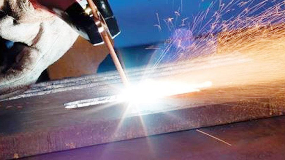
Image by theengineeringchoice
Fundamentals of Arc Initiation in Stick Welding
Stick welding relies on establishing an electrical arc between the electrode and the workpiece to melt the rod and base metal, forming a weld pool protected by slag.
The arc requires a voltage surge—typically 60-90 volts open circuit—to ionize the air gap and initiate current flow. Once started, the arc voltage drops to 20-35 volts for stability.
Key to arc initiation is the electrode’s coating, which aids in ionization and provides flux. For example, E6010 electrodes excel in DC positive polarity for deep penetration on rusty surfaces, while E7018 prefers AC or DC reverse for low-hydrogen applications.
Polarity affects arc behavior: direct current electrode positive (DCEP) concentrates heat on the workpiece for better penetration, whereas direct current electrode negative (DCEN) focuses heat on the electrode, increasing deposition rates but reducing penetration.
If the welder doesn’t arc, the circuit is incomplete or the voltage insufficient. Material compatibility plays a role; welding high-carbon steels demands higher amperage to overcome resistance, while aluminum requires specialized rods and often AC for oxide removal.
Diagnosing Electrical Circuit Issues
Start diagnostics by verifying the power supply and connections, as these account for over 50% of no-arc problems. Inspect the input power: ensure the welder is plugged into a dedicated circuit rated for its amperage draw—typically 20-50 amps for 120V units or 50-100 amps for 240V models. Voltage fluctuations from shared circuits can drop below the threshold needed for arc initiation.
Check cable integrity. Work clamp connections must be clean and tight; oxidation on the clamp jaws increases resistance, preventing current flow. Measure resistance with a multimeter—aim for under 0.5 ohms from stinger to workpiece. Electrode holders with worn springs fail to grip rods securely, leading to intermittent contact.
Polarity mismatches exacerbate issues. For cellulosic electrodes like E6011, DCEN might cause erratic arcing on thin materials due to excessive electrode melt-off. Switch to DCEP for stability.
Quantify setup: for a 1/8-inch rod, set amperage to 90-140 amps, depending on position—flat welds tolerate higher settings for faster travel speeds.
Electrode and Consumable Factors
Electrodes themselves often cause no-arc scenarios. Moisture-absorbed rods, especially low-hydrogen types like E7018, develop porous coatings that hinder ionization.
Bake suspect rods at 250-300°F for two hours to restore performance; improper storage in humid environments leads to hydrogen cracking risks beyond just arcing failures.
Rod diameter influences arc start. Oversized rods for the welder’s output rating demand more amperage than available, resulting in sticking without arcing. Reference this table for standard ranges:
| Rod Diameter (inches) | Amperage Range (DC) | Typical Applications |
|---|---|---|
| 3/32 | 40-90 | Thin sheet metal, overhead positions |
| 1/8 | 75-185 | General fabrication, vertical welds |
| 5/32 | 110-230 | Heavy plate, deep penetration |
| 3/16 | 140-305 | Structural beams, high-strength steels |
Select based on material thickness; for 1/4-inch mild steel, a 1/8-inch E7014 rod at 120 amps ensures smooth starts. Slag from previous welds on the electrode tip insulates the core, blocking contact—scratch-start techniques help, but clean tips for reliability.
Incompatible electrodes for the power source worsen issues. AC-only welders struggle with DC-specific rods due to waveform differences; AC provides easier starts on magnetized materials but less control over penetration.
Machine Settings and Calibration Problems
Improper settings disrupt arc formation. Amperage too low fails to generate sufficient heat for ionization—start at the manufacturer’s midpoint for the rod size and adjust upward in 10-amp increments. For instance, a 140-amp welder maxed out on a 5/32-inch rod might not arc if set below 110 amps, as the voltage can’t bridge the gap.
Duty cycle limitations cause intermittent no-arc if the machine overheats. A 20% duty cycle at 100 amps means only 2 minutes of continuous welding per 10-minute cycle; exceeding this trips thermal protection, cutting output. Monitor temperature indicators and allow cooldown.
Calibration drift in older units skews output. Use a clamp meter to verify actual amperage against the dial—discrepancies over 10% indicate internal issues like faulty rectifiers in inverter models.
For transformer-based welders, worn brushes or loose windings increase impedance, reducing open-circuit voltage below 50 volts, insufficient for arcing.
Grounding and Workpiece Preparation
Poor grounding ranks high in no-arc causes. The work clamp must contact bare metal; paint, rust, or mill scale insulates, raising resistance. Grind a clean spot at least 2 inches square for attachment, ensuring direct metal-to-metal contact.
Workpiece material affects arcing. High-alloy steels like stainless require higher voltages due to greater electrical resistance; use E308-16 rods with DCEP at 100-150 amps for 1/8-inch diameter.
Joint preparation influences this—bevel edges for better access, but excessive gaps (over 1/16 inch) make arcing harder as the arc stretches.
Position impacts start reliability. Overhead welding demands quick, decisive strikes to avoid rod sticking; reduce amperage by 10-20% from flat settings to control the pool. Travel speed ties in: too slow allows slag to interfere, while too fast prevents sustained arcing.
Environmental and Interference Factors
External conditions can prevent arcing. Wind disperses shielding gas in hybrid setups or ionizes air unpredictably outdoors; shield the arc with barriers for consistency. Electromagnetic interference from nearby equipment—like plasma cutters—disrupts inverter electronics, causing voltage spikes or drops.
Humidity affects electrode performance, as mentioned, but also machine internals. Condensation in conduits shorts circuits; store welders in dry areas and use dehumidifiers in coastal U.S. shops. Power quality from generators must match—ensure stable 60Hz output without surges.
In one shop scenario, switching from a worn extension cord to direct plugging resolved intermittent no-arc, as voltage drop exceeded 10% over 50 feet.
Another insight: for portable units, battery-powered starts assist in remote locations where grid power fluctuates.
Advanced Troubleshooting Techniques
For persistent issues, employ systematic testing. Isolate components: swap cables, electrodes, and even machines if available. Use an oscilloscope for arc voltage waveforms—ideal starts show a sharp peak followed by steady oscillation.
Internal faults like blown diodes in rectifier bridges manifest as no output. Test with a multimeter in diode mode; forward bias should read 0.3-0.7 volts. Capacitor failures in inverters cause ripple, preventing clean arcing—replace if capacitance drops below spec.
Firmware updates for digital welders address software bugs affecting arc initiation algorithms. Check manufacturer sites for models like Lincoln Electric’s Invertec series.
Preventive Maintenance for Arc Reliability
To prevent stick welder not arcing issues, establish a maintenance routine focused on electrical integrity and consumable management.
Regularly inspect connections for corrosion, tightening clamps and replacing cables every 6-12 months in high-use environments. Calibrate settings quarterly using certified meters to ensure output accuracy, as drift can accumulate unnoticed.
Store electrodes in rod ovens or sealed containers to maintain low moisture levels, particularly for critical low-hydrogen applications. Match rod selection to job specifics—avoid universal rods for specialized materials to minimize compatibility failures. Monitor duty cycles during extended sessions, incorporating breaks to avoid thermal shutdowns.
In U.S. shops, comply with OSHA guidelines for electrical safety, grounding all equipment properly to reduce interference risks.
One advanced insight: integrating arc force controls on modern inverters allows automatic amperage boosts during starts, enhancing reliability on contaminated surfaces without manual adjustments. This optimization ensures deeper penetration and fewer defects, elevating overall weld quality.
FAQs
Why does my stick welder arc weakly on thick materials?
Weak arcing on thick plates often results from insufficient amperage or incorrect polarity. For 1/2-inch steel, use a 5/32-inch E7018 rod at 150-200 amps DCEP to achieve proper heat input. Clean the surface thoroughly, as scale increases resistance, demanding higher settings.
Can a faulty outlet cause no arc in my welder?
Yes, outlets with loose wiring or inadequate amperage rating interrupt power delivery. Test with a voltage meter under load; drops below 220V for 240V units prevent arc initiation. Upgrade to industrial-grade receptacles for sustained performance.
How does rod angle affect arcing issues?
Improper rod angle—over 15 degrees from perpendicular—lengthens the arc, raising voltage requirements and causing instability. Maintain 10-15 degrees drag angle for flat welds to ensure consistent contact and ionization.
What if my inverter welder won’t arc after storage?
Storage in cold or humid conditions can cause component contraction or moisture ingress. Warm the unit gradually and dry internals if needed. Check error codes; many inverters display faults for capacitor issues.
Is AC better than DC for avoiding no-arc problems?
AC facilitates easier starts on magnetized or oxidized materials due to alternating polarity, but DC offers superior control for most fabrications. Choose based on rod type—AC for E7024 irons, DC for precision work.