
Many fabricators run into the same bottleneck: a solid stick welder handles repairs and fabrication perfectly, yet clean, fast metal cuts remain a grind, literally, with angle grinders or oxy-fuel setups that leave slag, distortion, and hours of cleanup.
The search for “how to make a plasma cutter from an arc welder” arises because a commercial 40–60 A unit starts at $500–$1,200 while most shops already own a heavy transformer welder gathering dust.
Converting the welder’s power supply into a plasma source delivers 200–400 VDC open-circuit voltage and a constricted plasma jet at 30–80 A, cutting ¼-inch mild steel at 10–15 inches per minute with kerf under 1/16 inch.
The upgrade matters for throughput: plasma reduces cut time by 5–8× versus mechanical methods while minimizing heat-affected zones on thin stock. Success hinges on precise electrical matching, not generic parts swaps.
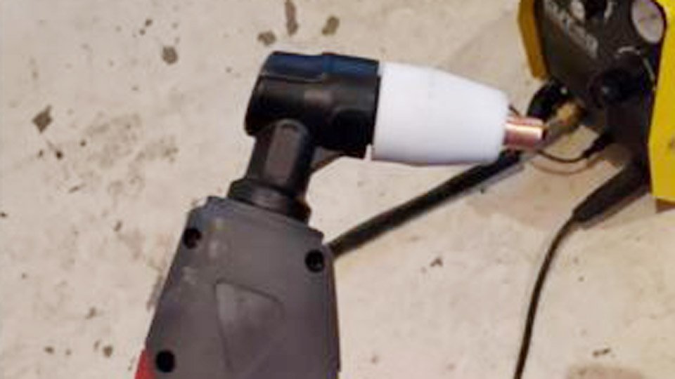
Image by reddit
Why Arc Welders and Plasma Cutters Demand Different Power Characteristics
Stick welders output constant-current DC or AC at 20–35 V under load with open-circuit voltage (OCV) typically 50–80 V. Plasma cutting requires a sustained 100–150 V arc voltage once established and 200–400 VDC OCV to maintain the plasma column across the nozzle-to-work gap.
The plasma jet operates at 12,000–20,000 A per square inch density, ionizing shop air into 40,000 °F plasma that expels molten metal at sonic speeds. A standard welder’s low OCV cannot reliably sustain this without additional voltage multiplication or energy storage.
Direct connection produces unstable arcs, excessive electrode wear, or no pilot arc at all. The conversion therefore adds rectification, capacitance, current limiting, and high-frequency (HF) starting to bridge the gap while preserving the welder’s transformer core for bulk current delivery.
Open Circuit Voltage and Arc Characteristics
Stick OCV peaks at 60–70 V on most 150–250 A machines; plasma power supplies deliver 250–350 V OCV to overcome the high-resistance gas column before the main arc transfers. Arc voltage under cut drops to 90–130 V depending on nozzle orifice (0.030–0.060 inch) and gas pressure. Without sufficient headroom, the plasma extinguishes mid-cut on thicker material or contaminated surfaces.
Current and Voltage Demands in Plasma Cutting
Typical DIY plasma draws 30–60 A at 100–120 V across the arc for ⅛–⅜ inch cuts—far lower amperage than stick welding but at double the voltage. Power (P = V × I) remains comparable to a 200 A welder output, yet the volt-amp curve must remain stiff to prevent voltage sag.
Transformer welders excel here because their leakage inductance naturally limits current; inverters often fold back or overheat under the sustained high-voltage load.
Selecting the Right Arc Welder for Conversion
Only transformer-based “buzz box” or engine-driven welders with 150 A+ rating and true constant-current output suit conversion. Inverter machines rarely work without major internal rewiring because their IGBTs and control boards cannot tolerate the reflected high-voltage spikes or altered duty cycles.
Transformer-Based vs Inverter Models
Old Lincoln AC-225, Miller Thunderbolt, or generic 200–300 A Chinese transformer units provide the necessary 20–30 V secondary winding that, after full-wave rectification and capacitor storage, yields 200+ VDC.
Inverters limit OCV to 50–65 V and lack the magnetic mass to handle continuous plasma duty without thermal shutdown. Parallel two identical transformer machines if you need 80 A+ output for ½-inch plate.
Minimum Power Ratings for Viable Cutting
Target 180–250 A rated output at 60 % duty cycle for reliable 40–60 A plasma operation. A 3 kVA transformer delivers sufficient headroom after 20–30 % losses in rectification and limiting resistors. Lower-rated units cut ⅛-inch material but overheat after 3–5 minutes continuous duty.
Core Components You’ll Need to Source or Build
Focus procurement on high-current, high-voltage-rated parts that match the welder’s secondary output (typically 24–48 VAC open circuit).
Plasma Torch and Consumables
Use a standard non-pilot or blow-back torch rated 40–60 A (e.g., compatible with Hypertherm-style consumables). Orifice size 0.035–0.045 inch for 30–50 A cuts. Stock 10–20 electrodes and nozzles; expect 50–150 pierces per set depending on air dryness and amperage. Torch lead length under 15 ft minimizes voltage drop.
High-Frequency Pilot Arc Starter
A flyback transformer scavenged from an old CRT TV or monitor, driven by a simple 555 timer, MOSFET driver, or ignition-coil circuit, produces 20–50 kV at 15–30 kHz to ionize the air gap.
Mount the flyback secondary in series with the torch electrode lead via a 0.001–0.01 µF high-voltage capacitor to isolate once the main arc transfers. Reed-switch or current-transformer sensing disables HF after 0.1–0.5 seconds of stable cut current.
Rectification and Energy Storage
Install a 200–300 A, 600–1000 V bridge rectifier (stud-mount with heatsinks) directly across the welder secondary. Follow with a capacitor bank of 2000–5000 µF at 400–450 VDC (paralleled electrolytic or oil-filled motor-run caps).
This bank supplies the surge current needed for piercing and stabilizes voltage sag. Add a 5–10 Ω, 500–1000 W current-limiting resistor (nichrome wire or paralleled water-heater elements) in series to prevent transformer saturation and limit peak current to 60–80 A.
Compressed Air and Trigger System
Shop compressor at 90–120 PSI regulated to 25–40 PSI at the torch. Install a 24 V solenoid valve triggered by the torch switch. Use ¼-inch ID hose with moisture separator and coalescing filter; water in the air destroys consumables in under 10 cuts.
Building the Modified Power Supply
Mount all high-current components on a non-conductive panel with 10–12 gauge wire for secondaries and 4–6 gauge for torch leads. Ground the welder chassis and workpiece clamp separately to prevent floating potentials.
Integrating the Rectifier and Capacitors
Connect welder secondary leads to the bridge AC inputs. Positive DC output goes through the limiting resistor to the positive capacitor bus, then to the torch electrode. Negative bus connects to the workpiece clamp.
Bleed resistors (100 kΩ, 5 W) across each capacitor prevent stored charge hazards after shutdown. Expect 280–340 VDC open circuit after rectification of a 40 VAC secondary.
Adding the Flyback High-Voltage Circuit
Power the flyback driver from a separate 12–24 V low-voltage supply or tap the welder’s fan circuit. Route the HV output through a high-voltage diode and coupling capacitor to the torch electrode lead.
Trigger the driver simultaneously with the torch switch; current sensing (reed relay or CT + comparator) shorts the HV output once main current exceeds 10–15 A.
Assembling and Wiring the Complete System
Route all high-voltage leads in shielded cable or conduit. Torch trigger controls both air solenoid and main contactor (if your welder lacks one). Set welder amperage dial to 40–60 % of maximum output; the resistor and plasma load will dictate actual current. Test continuity and polarity before first power-up: electrode positive, workpiece negative.
Torch Connections and Grounding
Electrode lead carries +DC plus superimposed HF. Shield gas/air line runs coaxial inside the torch cable. Work clamp must make solid contact within 4–6 ft of the cut to minimize voltage drop and arc wander.
Control Circuit for Safe Operation
A simple relay or solid-state contactor energizes the welder primary only when the torch trigger is pressed and air pressure confirms via a pressure switch. This prevents dry-firing the transformer.
Optimal Cutting Parameters and Settings
Match amperage, pressure, and speed to material thickness for dross-free cuts and maximum consumable life.
| Material | Thickness (inch) | Amps | Air Pressure (PSI) | Travel Speed (IPM) | Nozzle Orifice |
|---|---|---|---|---|---|
| Mild Steel | ⅛ | 30–35 | 25–30 | 18–25 | 0.035 |
| Mild Steel | ¼ | 40–50 | 30–35 | 12–18 | 0.040 |
| Mild Steel | ⅜ | 55–65 | 35–40 | 8–12 | 0.045 |
| Stainless | ⅛ | 35–40 | 28–32 | 15–20 | 0.035 |
| Aluminum | ¼ | 45–55 | 30–35 | 10–15 | 0.040 |
Pierce at 1.5× cutting amps for 1–2 seconds standoff, then lower to cut height (⅛–3/16 inch). Dry air below 40 °F dew point extends consumable life 3×.
Real-World Performance and Limitations
A converted 200 A transformer welder reliably cuts ¼-inch mild steel continuously for 4–6 minutes before thermal limiting kicks in—comparable to a 40 A dedicated cutter. Kerf width stays 0.050–0.070 inch with clean edges on flat stock; bevel angle runs 3–6° without shielding gas.
Expect 50–70 % duty cycle at 50 A due to resistor heat and welder cooling. Thicker material (½ inch+) requires 80 A+ output and slower speeds, pushing the transformer near saturation.
Cut Quality Expectations
With filtered air and correct standoff, cuts require minimal cleanup—far superior to carbon-arc gouging or oxy-fuel. Stainless and aluminum show slight dross on the bottom edge that wire-brushes off easily.
Duty Cycle and Overheating Management
Monitor welder temperature; add auxiliary fans if running production. The limiting resistor dissipates 1–2 kW—mount it on a heatsink or in oil for sustained runs.
Troubleshooting Common Conversion Issues
Arc Starting Failures
If the pilot spark is weak, increase flyback drive frequency or check coupling capacitor value. Contaminated air or worn nozzle prevents ionization.
Unstable Plasma Jet
Voltage sag below 90 V under load indicates insufficient capacitance or excessive resistance—add 1000 µF or reduce limiting resistor by 2 Ω. Air pressure too high causes turbulence and arc wander.
Decision-Making Summary for Shop Use
Choose a transformer welder rated 200 A+ with accessible secondary terminals and pair it with a commercial 40–60 A torch plus flyback starter for a system that cuts ¼-inch plate at costs under $150 in parts.
The conversion yields performance matching entry-level commercial cutters while retaining full stick capability by simply unplugging the torch leads.
Pro-level insight: once the base conversion runs, add a variable SCR phase-control module on the primary side for true infinite amperage adjustment—turning the same rig into a precision cutter for 16-gauge sheet to ½-inch structural without swapping resistors or risking transformer saturation.

Hi, I’m Zachary Ford. I’m passionate about welding and dedicated to helping both beginners and experienced welders make informed decisions. I research, test, and write about welding helmets, welding machines, safety equipment, and essential workshop tools. My goal is to provide honest reviews, practical buying guides, and easy-to-follow tutorials that help you weld more safely, work more efficiently, and choose the right gear with confidence.