You’re butt-welding 3 mm stainless tubing or chasing single-pass penetration on 6 mm carbon steel plate, and standard TIG leaves you fighting distortion, slow travel speeds, or multiple passes with filler. The difference comes down to plasma in plasma arc welding (PAW).
Plasma here is the constricted, ionized gas column forced through a copper nozzle at near-sonic velocity, delivering energy densities far higher than a free TIG arc.
This column reaches temperatures approaching 28,000 °C while maintaining a stiff, columnar shape that resists wander even at longer arc lengths.
Understanding its formation, control variables, and behavior directly dictates penetration consistency, bead profile, and production speed—critical decisions for both automated shop setups and manual hobbyist work.
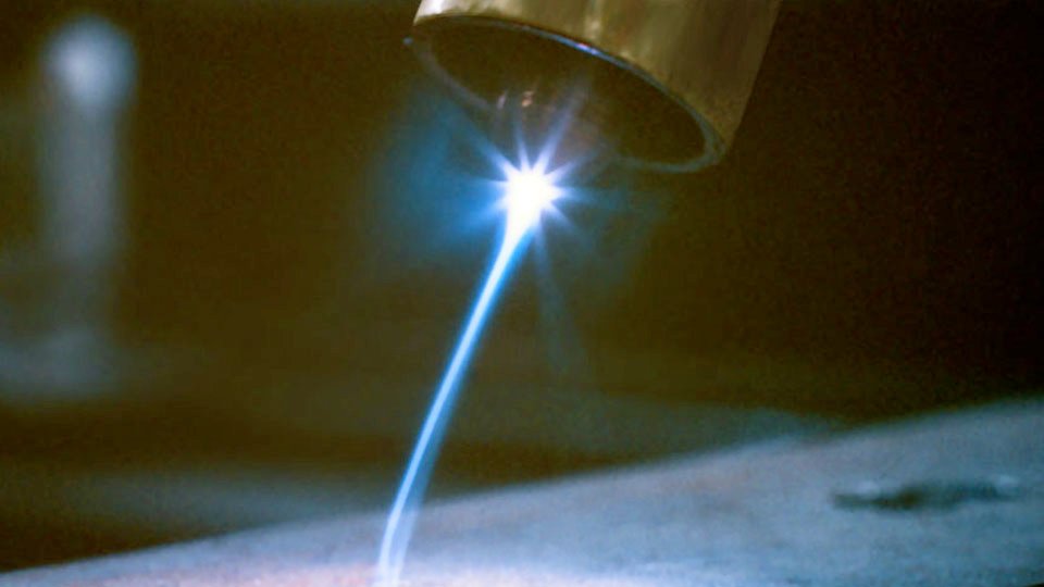
Image by fsmdirect
How Plasma Forms and Behaves in the PAW Torch
The Ionization Process and Arc Constriction Mechanism
Plasma forms when plasma gas—typically pure argon—passes through the electric arc inside the torch. A pilot arc first ionizes the gas between the tungsten electrode (cathode) and the water-cooled copper nozzle (anode in pilot mode). Free electrons accelerate, colliding with neutral atoms and stripping more electrons in an avalanche.
The resulting mix of ions, electrons, and excited atoms conducts current efficiently. The key step is constriction: the fine-bore nozzle (0.062–0.125 in. diameter depending on current) squeezes the arc column, raising current density and velocity.
Plasma exits the orifice at speeds approaching the speed of sound, creating a focused jet instead of the bell-shaped TIG arc. This constriction increases voltage (typically 27–31 V versus 15–20 V in TIG at the same current) and concentrates heat input into a narrow footprint.
Temperature, Velocity, and Energy Density Compared to Conventional Arcs
The constricted plasma jet operates at 20,000–28,000 °C core temperature with energy densities 5–10 times higher than a TIG arc of identical amperage. Velocity reaches 300–1,000 m/s at the nozzle exit, imparting significant arc force that depresses the weld pool.
In contrast, a TIG arc at 100 A spreads heat over a wider area, producing shallower penetration and greater heat-affected zone (HAZ) width.
PAW’s columnar shape tolerates arc-length variations up to 20 mm in microplasma mode without instability, giving operators more forgiveness on fit-up or automated torch height control. These characteristics translate directly into single-pass capability on thicker material and reduced distortion on thin sheet.
Transferred vs. Non-Transferred Plasma Arcs: Critical Setup Choices
Technical Differences and Application Guidelines
Transferred arcs route current from the tungsten electrode through the workpiece, delivering maximum heat to the joint. This is the standard mode for all fusion welding because the workpiece becomes the anode and receives roughly two-thirds of the arc heat.
Non-transferred arcs keep current between electrode and nozzle; the plasma jet carries heat outward without completing the circuit through the plate.
Use non-transferred mode only for pilot arc maintenance or when welding non-conductive coatings or very thin materials where direct current flow risks burn-through. Most production PAW systems start with a non-transferred pilot (5–50 A) then switch to transferred mode automatically upon arc transfer.
Pilot Arc Role in Reliable Starts and Torch Life
The pilot arc pre-ionizes the plasma gas path, eliminating high-frequency start interference with CNC controllers or nearby electronics. Once the torch approaches the workpiece (stand-off 3–6 mm), main current transfers and the pilot extinguishes. This sequence prevents electrode contamination and allows repeatable starts at currents as low as 0.5 A.
Electrode setback (distance from electrode tip to nozzle orifice) must stay at maximum for keyhole work or minimum for melt-in to balance arc stability and nozzle life. Incorrect setback is the most common cause of double-arcing and premature nozzle erosion.
Selecting Plasma Gases for Optimal Arc Performance
Argon: Baseline Stability and Versatility
Pure argon remains the default plasma gas because of its low ionization potential (15.8 eV), reliable arc initiation, and inert nature across all temperatures. Flow rates range 0.25–5 SCFH (0.12–2.4 lpm) for most tips; higher flows constrict the jet further but risk undercutting if not balanced with travel speed.
Argon produces a stiff, narrow column ideal for microplasma and medium-current work on carbon steels, stainless, and titanium. Shielding gas stays separate—usually argon or argon/helium—to protect the solidifying pool without interfering with plasma constriction.
Argon-Hydrogen Mixtures: Heat Input and Oxide Control for Specific Alloys
Adding 5–15 % hydrogen to argon (plasma or shield) increases thermal conductivity and arc voltage, raising heat input to the pool by 20–30 % at the same current. Hydrogen reduces surface tension, improves wetting, and acts as a reducing agent on stainless and nickel alloys, minimizing oxide inclusions. On austenitic stainless, 5 % hydrogen mixtures allow 10–15 % higher travel speeds while preventing undercut.
Limit hydrogen to 5 % or less on thicker sections (>4 mm) to avoid hydrogen embrittlement. Never use Ar/H₂ on aluminum or reactive metals; stick to pure argon or argon/helium. Helium additions broaden the heat pattern for cover passes but lower plasma jet stiffness.
Operating Modes and Current Ranges That Define Plasma Behavior
Microplasma for Thin Materials and Precision Work
Operate 0.1–15 A with plasma flows 0.2–0.5 lpm. The arc remains stable across 20 mm length variations, making it perfect for 0.1–2.4 mm sheet, wire mesh, or edge welds on medical tubing. Heat input stays low enough for minimal distortion on 0.005 in. titanium foil. Manual control is feasible here; the stiff column tolerates minor torch wobble.
Medium-Current Mode for TIG-Like but Stiffer Performance
Run 15–200 A with 0.5–1.5 lpm plasma flow. Characteristics mirror TIG but with higher voltage and narrower bead. Use for 2–6 mm material where full penetration without keyhole is desired. Arc force is moderate, allowing filler addition and positional work with pulsing.
Keyhole Mode: Parameters for Full Penetration Without Grooves
Above 100 A (typically 150–350 A) and plasma flows 1.5–3.5 lpm, the jet creates a through-hole that the molten pool flows around and closes behind the torch. Square-butt joints up to 10 mm thick weld in one pass at 10–25 ipm.
Balance current, flow, and travel speed precisely: too much flow blows metal out; too little collapses the keyhole. Visual confirmation of a stable keyhole (visible light through the root) is the only reliable in-process indicator.
Key Process Variables Controlling Plasma Jet Stability
Plasma gas flow rate, nozzle orifice diameter, electrode setback, and stand-off distance interact nonlinearly. Increasing flow or decreasing orifice size raises arc pressure and penetration but narrows the operating window.
Typical electrode setback: maximum (flush with nozzle rear) for keyhole; minimum (recessed 0.030–0.060 in.) for melt-in to soften the jet. Stand-off of 3–6 mm keeps the jet focused without nozzle contact. Current pulsing (1–20 kHz) synchronizes with travel speed to stabilize the keyhole on positional or circumferential welds. Any deviation >10 % in flow or >5 % in current can lose the keyhole mid-weld.
Plasma Arc Welding Parameters for Common Materials and Thicknesses
Use the table below as starting points for mechanized setups on square-butt joints. Adjust ±10–15 % for manual work, joint fit-up, or specific alloys. Most steels need 10–15 % higher current than stainless at equal speed. Shield gas flow remains 10–20 SCFH argon or Ar/5H₂.
| Material & Thickness | Current (A) | Plasma Gas Flow SCFH (lpm) | Travel Speed ipm (mm/min) | Tip Size (in.) |
|---|---|---|---|---|
| Stainless 20 ga (0.035 in.) | 40–60 | 0.75–1.25 (0.35–0.59) | 20–25 (508–635) | 0.062 / 0.081 |
| Stainless 16 ga (0.062 in.) | 50–70 | 0.75–1.25 (0.35–0.59) | 20–25 (508–635) | 0.081 / 0.093 |
| Stainless 11 ga (0.120 in.) | 100–115 | 1.0–1.5 (0.47–0.71) | 25–30 (635–762) | 0.093 |
| Carbon Steel 1/8 in. (3.2 mm) | 110–130 | 1.5–2.5 (0.71–1.18) | 12–18 (305–457) | 0.093–0.125 |
| Stainless 1/4 in. (6.4 mm) keyhole | 180–250 | 2.5–4.0 (1.18–1.89) | 10–15 (254–381) | 0.125 |
For aluminum, switch to DCEP polarity with water-cooled electrode and pure argon; currents run 15–20 % higher than stainless equivalents because of higher thermal conductivity.
Decision Factors: When Plasma Arc Outperforms Other Processes
Plasma delivers 2–3× travel speed versus TIG on 3–8 mm plate with 50–70 % less heat input, producing narrower HAZ and less distortion. Keyhole mode eliminates groove preparation and filler on single-pass joints, cutting labor and material costs in pipe shops or pressure vessel fabrication.
Setup cost is higher (dedicated torch, coolant system, precise flow control), but payback occurs quickly on repetitive production. For one-off hobbyist work under 3 mm, TIG remains simpler.
Automated PAW with seam tracking and current pulsing extends the sweet spot to positional welding on 6–10 mm pipe where TIG would require multiple passes.
Final Thoughts
Match plasma mode, gas mixture, and flow to material thickness and joint type first—then lock current and speed. On 4–8 mm stainless or carbon steel, keyhole PAW with Ar/5H₂ shielding routinely achieves 100 % penetration at 12–18 ipm with under 1 mm cap reinforcement and zero filler.
The advanced insight pros rely on: synchronize 2–5 Hz current downslope with plasma flow taper at weld termination to collapse the keyhole gradually, eliminating root concavity and porosity that plague abrupt stops on automated circumferential seams. This single adjustment often separates consistent X-ray quality from scrap.