Resistance spot welding is a fast, repeatable joining process used across sheet metal fabrication, automotive panels, and production welding lines. But how does resistance spot welding work in practical terms, and why does it matter for weld quality?
The process relies on controlled electrical resistance, high current, and electrode pressure to generate localized heat at the joint interface.
If parameters like amperage, squeeze force, or weld time are off, the result can be weak nuggets, expulsion, surface burning, or inconsistent joint strength—leading to rework and failed inspections.
Understanding the underlying mechanism is critical for achieving proper fusion without distortion or material damage, especially in thin-gauge metals. It directly affects production efficiency, energy use, and weld consistency in high-volume environments.
In this guide I’ll break down the working principle, key variables, and what actually happens at the weld interface—so you can make precise adjustments and produce reliable, defect-free spot welds.
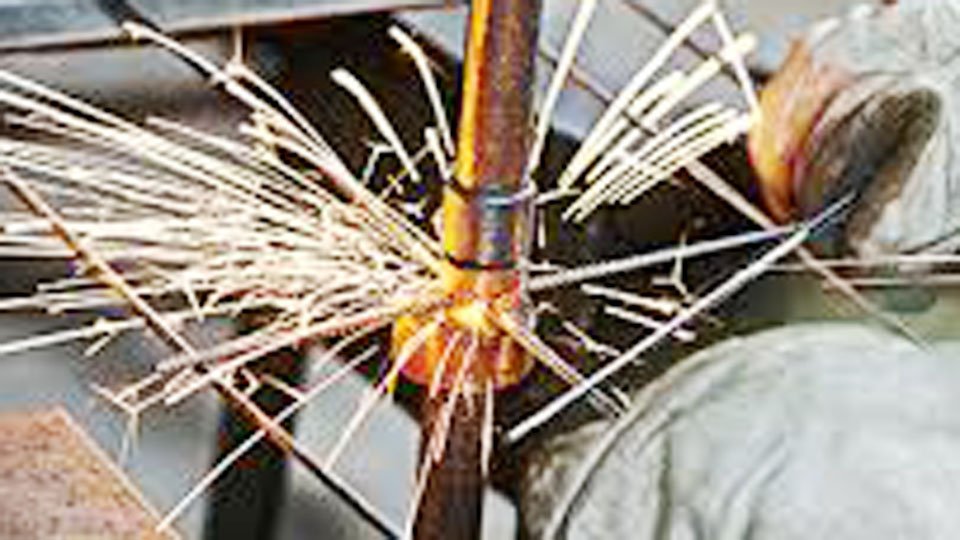
Image by schuettemetals
The Core Mechanism: How Resistance Spot Welding Generates Heat and Forms the Nugget
Resistance spot welding operates on Joule’s law of heating: heat input equals current squared times resistance times time (Q = I²Rt). The majority of heat develops exactly where it is needed—at the faying surface between the two sheets—because contact resistance there far exceeds the bulk resistance of the sheets or the low-resistance copper electrodes.
Joule Heating and Contact Resistance Dynamics
Current flows from one copper electrode through the top sheet, across the interface, through the bottom sheet, and into the opposite electrode.
The seven resistances in the circuit—electrode bulk, electrode-to-sheet contact (two locations), sheet bulk (two locations), and the dominant sheet-to-sheet contact—create a positive feedback loop in steel.
As temperature rises, steel resistivity increases relative to copper, concentrating even more heat at the interface. Within a fraction of a second the interface reaches melting temperature while the electrodes remain relatively cool and act as heat sinks.
The molten pool grows into a lens-shaped nugget that solidifies under continued pressure, forging the joint metallurgically without filler.
Role of Electrode Force in Heat Concentration
Force does more than hold parts together. It collapses surface asperities, reducing initial contact resistance and preventing arcing while ensuring current density remains high enough for rapid nugget formation.
Too little force allows expulsion; too much flattens the contact area, lowering density and producing undersized nuggets.
Real-world setups balance these effects so the nugget diameter reaches at least 5√t (where t is the thickness of the thinner sheet) for acceptable shear strength.
The Welding Cycle Explained – From Squeeze to Hold
Every resistance spot weld follows a precise four-stage cycle controlled by the machine timer. Each stage directly influences nugget formation and final joint properties.
Squeeze Time and Initial Contact
Squeeze time (typically 3–10 cycles) allows the electrodes to close, build full force, and stabilize the stack-up. This period eliminates any air gaps or misalignment that would create erratic resistance. In high-volume production, insufficient squeeze time is a leading cause of inconsistent button size.
Weld Time – Current Application and Nugget Growth
Weld time (measured in 50 or 60 Hz cycles) controls how long the high-amperage pulse flows. For 0.8 mm mild steel the typical range is 8 cycles at 9,000 A.
Shorter times with higher current suit aluminum; longer times with lower current suit high-strength steels to avoid cracking. Nugget growth is not linear—most expansion occurs in the final third of the weld time once the interface resistance drops and bulk heating dominates.
Hold Time for Solidification Under Pressure
Hold time (usually 1–6 cycles) maintains forging pressure while the nugget cools below the solidus. This prevents shrinkage voids and ensures the forged structure develops maximum strength. Releasing force too early allows the nugget to pull apart internally under thermal contraction.
Setting the Three Critical Parameters for Consistent Welds
Force, current, and time (FCT) are interdependent. Change one and you must adjust the others to stay inside the weld lobe—the process window that produces acceptable nuggets.
Choosing Weld Current Based on Material and Thickness
Current determines heat input. For mild steel the rule of thumb starts around 8–12 kA and scales with thickness. The table below gives practical starting points for equal-thickness mild steel on single-phase AC equipment (50 Hz cycles).
| Sheet Thickness (mm) | Electrode Force (kN) | Weld Current (A) | Weld Time (cycles) | Hold Time (cycles) | Electrode Diameter (mm) |
|---|---|---|---|---|---|
| 0.63 + 0.63 | 2.00 | 8,500 | 6 | 1 | 6 |
| 0.80 + 0.80 | 2.24 | 9,000 | 8 | 2 | 6 |
| 1.00 + 1.00 | 2.50 | 9,500 | 10 | 2 | 6 |
| 1.25 + 1.25 | 3.15 | 10,000 | 13 | 3 | 6–7 |
| 1.60 + 1.60 | 4.00 | 10,600 | 16 | 3 | 6–7 |
| 2.00 + 2.00 | 5.00 | 11,200 | 3×7+2 | 4 | 7–8 |
Interpolate for intermediate thicknesses. Coated steels or higher-strength grades require coated-parameter adjustments—usually higher force and slightly longer time with reduced current to protect the coating.
Electrode Force Requirements and Adjustments
Force must overcome springback and maintain contact throughout the cycle. Start at 2–3 kN for thin mild steel and increase roughly with the square root of thickness. Servo-driven guns allow real-time force profiling—ramping up during weld time to suppress expulsion once the nugget is molten.
Weld Time in Cycles – Timing for Optimal Nugget Size
Weld time controls heat duration. One cycle at 60 Hz equals 16.7 ms; at 50 Hz it is 20 ms. Aim for nugget diameter of 5√t minimum. For 1 mm sheet that means at least 5 mm. Destructive testing (peel or chisel) confirms you are inside the lobe before production runs begin.
Electrode Selection and Maintenance for Reliable Performance
Electrodes transfer current, apply force, and remove heat. Wrong choice or poor maintenance collapses the entire process.
RWMA Electrode Classes and Materials
RWMA Class 2 (copper-chromium) is the workhorse for mild and galvanized steel because it balances conductivity and hardness. Class 1 suits aluminum where maximum conductivity prevents sticking. Refractory electrodes (Group B) handle extreme wear on coated or stainless materials.
Tip Geometries and Their Impact on Current Density
Domed (radiused) tips concentrate current for thin sheets and reduce surface marking. Truncated cone or flat-face tips suit thicker material or when precise indentation control is required. Face diameter directly affects current density: smaller diameter raises density and speeds nugget formation but accelerates mushrooming.
When and How to Dress or Replace Electrodes
Mushrooming increases contact area, drops current density, and shrinks the nugget. Dress every 200–500 welds on mild steel, every 50–100 on aluminum or heavily coated stock. Use a hand-held tip dresser or automated system; never file manually. Replace when shank diameter reaches 1.5× original face size.
Adapting Resistance Spot Welding to Different Materials
Material resistivity, conductivity, and surface condition dictate parameter shifts.
Low Carbon Steel – Baseline Settings
Mild steel offers the widest process window. Baseline parameters from the table above produce consistent 5–7 mm nuggets with minimal expulsion when parts fit-up is good.
Coated Steels (Galvanized) – Adjustments for Zinc Coating
Zinc vaporizes at 420 °C—well below steel melting point—creating expulsion risk. Increase force by 20–30 %, reduce current slightly, and add a short upslope (1–2 cycles) to burn through the coating gradually. Galvanized-to-galvanized stacks often need pulsation schedules to manage alloying at the electrode face.
Aluminum Alloys – High Current, Short Time Challenges
Aluminum’s high conductivity demands 2–3× the current of steel but only 20–40 % of the weld time. For 1.2 mm mill-finished sheet expect 22–28 kA, 2–5 cycles, and 3–5 kN force.
Oxide removal before welding or inverter DC with upslope is essential; AC machines struggle with consistency. Electrode sticking is the primary failure mode—frequent dressing with Class 1 tips is mandatory.
Diagnosing and Fixing Weld Quality Problems
Quality issues appear as undersized nuggets, expulsion, cracking, or surface defects. Each maps directly to FCT imbalance.
Undersized or Missing Nugget – Parameter Tweaks
Low current or short weld time fails to reach melting temperature. Increase current 5–10 % or add 1–2 cycles while monitoring for expulsion. Dirty surfaces or heavy oxide raise contact resistance unpredictably—clean parts solve many “cold weld” complaints.
Expulsion and Spatter – Containment Strategies
Expulsion signals excess heat or insufficient force once the nugget is liquid. Drop current, raise force, shorten weld time, or add a downslope. Poor fit-up or edge proximity also triggers it; maintain 2× electrode diameter minimum edge distance.
Surface Indentation and Cracking – Force and Cooling Factors
Excessive force or long hold time on thin material creates deep indentations. Reduce force after nugget formation if your machine supports dual-force schedules. Cracking in high-carbon or AHSS grades responds to pulsation or post-heat cycles that slow cooling.
Advanced Considerations for Professional Results
Heat Balance in Dissimilar Thicknesses
When thicknesses differ by more than 2:1, place the thicker sheet against the electrode with the larger face or switch to DC inverter for unidirectional current flow. This compensates for asymmetric heating.
Shunt Current Effects in Multi-Spot Applications
Welds spaced closer than 4–6× electrode diameter rob current from subsequent spots. Increase current 10–15 % or program a short off-time between welds to allow recovery.
Modern Controls – Inverter vs. AC Machines
Inverter (MFDC) machines deliver square-wave current with precise upslope and downslope control, reducing expulsion and energy use by roughly 10 % compared with AC. Dynamic resistance monitoring adjusts current in real time for electrode wear or fit-up variation—standard on modern automotive lines.
Performance-Based Takeaway
Resistance spot welding rewards precise FCT selection tailored to material resistivity and thickness. When nugget diameter consistently exceeds the 5√t minimum, shear strength routinely surpasses base-metal requirements while distortion stays below 0.5 mm on thin panels.
Professionals who map weld lobes for every new stack-up and dress electrodes on schedule achieve first-pass yields above 98 % in both hobby and production environments.
The advanced insight: integrate dynamic resistance feedback in inverter controls to compensate automatically for electrode wear and fit-up variation, turning a traditionally “blind” process into a data-driven, adaptive system that maintains quality even as conditions drift.
FAQs
What is the minimum nugget diameter for a quality resistance spot weld?
Use the 5√t rule where t is the thinner sheet thickness in mm. A 1 mm sheet requires at least 5 mm diameter; peel testing should pull a full button from one sheet.
How do welding parameters change when spot welding galvanized steel versus bare mild steel?
Galvanized material needs 20–30 % higher force, slightly lower current, and often a short upslope or pulsation to manage zinc vapor. Coated schedules from AWS C1.1 or equipment suppliers provide the exact starting points.
Why is aluminum more challenging to resistance spot welding than steel?
Aluminum’s low resistivity demands 2–3× higher current but only 20–40 % of the weld time. Oxide layers cause erratic contact resistance, and electrodes stick rapidly unless Class 1 copper is used and dressed frequently.
What causes expulsion during resistance spot welding and how do you prevent it?
Excess heat (high current or long weld time) combined with low force once the nugget is molten. Prevent it by raising force, shortening weld time, adding downslope, improving fit-up, or increasing edge distance to at least twice the electrode diameter.