Selecting the correct Maximum Fillet Weld Size for Plate Thickness is a technical requirement that directly affects weld integrity, heat input, and code compliance. Oversized fillet welds can introduce excessive heat, leading to distortion, increased residual stress, and unnecessary material cost.
Undersized welds, on the other hand, risk inadequate throat thickness, poor load distribution, and potential joint failure under service conditions.
In real fabrication, this balance influences amperage selection, travel speed, and overall arc stability. It also determines whether a weld will pass visual inspection or fail due to over-welding or lack of fusion at the root. Industry standards place limits on fillet weld size relative to base metal thickness for these exact reasons.
Understanding these limits helps welders and engineers produce structurally sound joints while avoiding rework, wasted filler metal, and inspection issues.
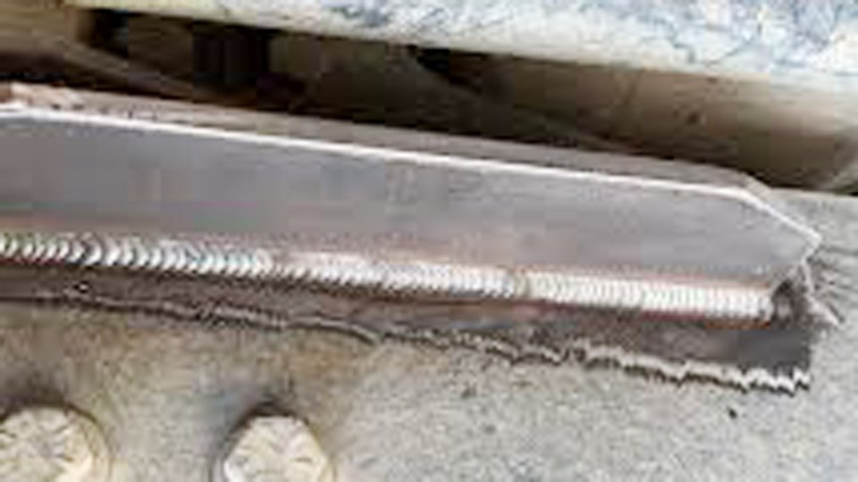
Image by structolution
Why Maximum Fillet Weld Size Depends on Plate Thickness
Plate thickness directly controls how much weld metal you can deposit before the joint geometry, heat input, or inspection criteria fail. Exceeding practical limits melts edges, creates excessive distortion, or produces welds stronger than the plate itself—wasting time and money.
The Inspection and Throat Integrity Challenge
Inspectors use fillet weld gauges to measure the shortest distance from the root to the hypotenuse (theoretical throat). When a fillet runs along the free edge of a plate in a lap joint, an oversized weld can melt that edge away.
The gauge then reads a false throat because the visible toe no longer aligns with the original plate corner. AWS D1.1 and AISC built the edge-limit rule precisely to keep that corner intact for accurate measurement and full effective throat.
Strength Limits Imposed by Base Metal
A fillet weld transfers load through shear on its throat. Once the leg size reaches roughly 0.75 times the thinner plate thickness (for typical 70-series electrodes), the plate itself becomes the weak link.
Larger welds add no capacity but increase shrinkage stress, distortion, and cost. The maximum useful size is therefore capped by the plate’s own shear capacity, not by arbitrary weld metal volume.
AWS D1.1 and AISC Rules for Maximum Fillet Weld Size
Structural codes set hard limits only where geometry and inspection demand them.
Specific Limits for Lap Joints Along Edges
Per AISC 360 Section J2.2b and AWS D1.1 (referenced in Figure 2.1 and commentary):
- For material thinner than ¼ inch (6 mm): maximum leg size equals the plate thickness.
- For material ¼ inch (6 mm) and thicker: maximum leg size equals plate thickness minus 1/16 inch (1.6 mm).
These values apply only along the edges of connected parts in lap joints. The 1/16-inch reduction leaves a visible land so inspectors can verify the toe location and confirm the throat dimension. If the drawing explicitly calls for “build-out to full throat thickness,” the limit is waived and the weld can be contoured outward.
When the Limit Does Not Apply
In T-joints, corner joints, or interior fillets not on a free edge, no code-imposed maximum leg size exists. You can deposit welds larger than plate thickness if the engineer requires it for fatigue or fit-up reasons. However, the base metal will still govern ultimate strength, so oversized fillets remain inefficient.
Drawing Designations for Full Throat Build-Out
When full strength demands a leg larger than the edge limit, note “weld to full throat” or “build-out permitted” on the drawing. This shifts responsibility to the engineer and allows multi-pass contouring that maintains the required throat while respecting edge geometry.
Calculating Required Fillet Weld Size for Structural Performance
Designers rarely need the absolute maximum weld; they need the minimum that carries the load. Yet understanding the upper practical limit prevents overwelding.
Rule of Thumb for Full Plate Strength
For a double-sided fillet in a T-joint using E70XX-class electrodes on ASTM A36 or similar mild steel, set leg size = 0.75 × thinner plate thickness. This produces an effective throat that matches the plate’s shear capacity.
Example: ½-inch plate to ⅝-inch plate → use ⅜-inch leg (0.75 × ½). The connection develops full plate strength without overwelding.
Effective Throat and Allowable Shear Stress
Effective throat = leg size × 0.707 (for 45° isosceles fillet).
Allowable shear stress on the weld (AISC) ≈ 0.3 × electrode tensile strength (21 ksi for E70).
Per linear inch of weld, capacity ≈ (throat × 21 ksi).
A quick field check: 1/16 inch of leg delivers approximately 0.927 kips per inch of length under longitudinal shear. Scale up from there and compare against plate capacity (0.6 × Fy × t × length).
Comparing Minimum vs. Maximum Practical Sizes
AWS D1.1 Table 7.7 (or older Table 5.8) sets minimum leg sizes based on the thicker part joined to ensure adequate heat input:
- Thinner than ¼ inch: ⅛ inch minimum
- ¼ to ½ inch: 3/16 inch minimum
- ½ to ¾ inch: ¼ inch minimum
- Over ¾ inch: 5/16 inch minimum
Minimum sizes prevent hydrogen cracking; maximum practical sizes (edge-limited or strength-limited) prevent waste and distortion. Between these two values lies the efficient operating range for most shop work.
Process-Specific Constraints on Fillet Weld Size
Code rules are theoretical. Arc physics imposes harder limits on what you can actually deposit in one pass.
Single-Pass Limits by Welding Process and Position
- SMAW (7018): practical single-pass maximum ≈ ¼ inch leg; 5/16 inch possible with 3/16-inch electrode but risks slag inclusions.
- GMAW/FCAW (0.045–1/16 inch wire): 5/16 inch common; up to ½ inch in flat or horizontal with larger wire and controlled heat input. AWS D1.1 Table 3.7 prequalified WPS often caps overhead at 5/16 inch.
- SAW: up to ½ inch or larger in flat position due to high deposition.
Exceeding these risks lack of fusion at the root, excessive convexity, or undercut.
Managing Heat Input on Thin Plates
On material under ¼ inch, even code-allowed maximum leg size can cause burn-through. Drop amperage, increase travel speed, or switch to pulsed GMAW. If distortion appears, back-step or use skip welding before pushing to maximum size.
Multi-Pass Techniques for Thick Material
For legs over ⅜ inch on thick plate, layer ⅛- to 3/16-inch passes. Clean between passes. Each layer must tie into the previous toe and root. This maintains the required throat while controlling heat input and residual stress.
Maximum Fillet Weld Size Chart by Plate Thickness
Use this reference for quick decisions (mild steel, lap or T-joints, E70 electrodes). Values are leg lengths.
| Plate Thickness (in) | Max Leg – Lap Edge (in) | Full-Strength Leg – Double Fillet T-Joint (in) | Typical Single-Pass Limit (in) | Notes |
|---|---|---|---|---|
| ⅛ | ⅛ | 3/32 | ⅛ | Edge limit governs |
| ¼ | ¼ | 3/16 | 3/16–¼ | Transition thickness |
| ⅜ | 5/16 | 9/32 | ¼–5/16 | Common bracket thickness |
| ½ | 7/16 | ⅜ | 5/16 | Full strength practical |
| ⅝ | 9/16 | 15/32 | 5/16 | Multi-pass often required |
| ¾ | 11/16 | 9/16 | ⅜ | Distortion risk rises |
| 1 | 15/16 | ¾ | ⅜–½ | Engineer approval needed for >⅝ leg |
Convert to mm as needed (1 in = 25.4 mm). Adjust downward 10–15 % for stainless or high-strength steels due to higher shrinkage.
Real-World Decision Making: When to Oversize or Undersize
Shop economics and service conditions often override pure code minimums or theoretical maximums.
Cost and Time Implications of Oversized Welds
A 5/16-inch fillet uses 56 % more weld metal than a ¼-inch fillet of the same length. Labor and consumables scale with the square of the leg size. On a 100-foot run, the difference can add hundreds of dollars and hours. Always verify actual load before defaulting to “bigger is better.”
Fatigue and Distortion Risks
Oversized fillets increase toe stress concentration and residual tensile stress. In cyclically loaded structures, this shortens fatigue life more than a properly sized weld. Excessive heat also bows thin plates; balance with clamping or peening.
Inspection and Quality Control for Fillet Welds
Using Fillet Weld Gauges Correctly
Convexity gauges and throat gauges must contact the actual toes. For edge-limited laps, confirm 1/16-inch land remains visible. Record undersize or oversize per AWS D1.1 Table 7.9 acceptance criteria—undersize is never acceptable; oversize is usually tolerated unless drawings prohibit it.
Acceptance Criteria for Size and Profile
Faces may be flat, slightly convex, or concave. Maximum convexity decreases with weld size (Table 7.9). Undercut ≤ 1/32 inch for most applications. Profile transitions must be gradual to avoid stress risers.
Adjustments for Different Materials and Applications
Mild steel follows the chart above. Stainless (3xx series) shrinks more—reduce leg size 10 % or use lower heat. Aluminum requires even tighter control due to high thermal conductivity; maximum practical legs drop quickly above ¼ inch plate.
High-strength low-alloy steels (A572 Gr. 50) follow the same edge limits but demand stricter preheat to avoid cracking when pushing toward maximum size.
Outdoor structural work in cold climates adds preheat requirements that indirectly limit single-pass size. Indoor non-structural hobby projects can safely ignore the 1/16-inch edge reduction if no inspector will measure the throat.
Performance-based Takeaway
Choose maximum fillet weld size for plate thickness by starting with the load requirement, applying the edge limit only where code demands it, then confirming process capability. The right size is the smallest that meets strength, passes inspection, and minimizes distortion and cost. Pros who master this consistently deliver lighter, stronger, and cheaper fabrications.
Advanced insight: In high-cycle fatigue applications, two smaller continuous fillets often outperform one oversized fillet because they distribute stress more evenly and reduce toe notch effects—proving that “maximum” is rarely the optimal engineering choice.