HVAC refrigerant lines endure extreme pressure swings, thermal cycling from -40°F to 250°F, and constant vibration from compressors. Soldered joints soften and crack under these conditions, leading to leaks that contaminate systems with oil and debris or trigger expensive callbacks.
Learning how to braze HVAC copper pipe without soldering solves this by creating metallurgical bonds that exceed base metal strength and maintain integrity at operating pressures above 500 psi.
Brazing uses filler metals that flow above 840°F, producing joints re-sistant to the demands of R-410A, R-32, or legacy refrigerants.
The process requires precise alloy selection, nitrogen purging, and heat control, decisions that separate reliable installs from failures that circulate scale through TXVs and compressors.
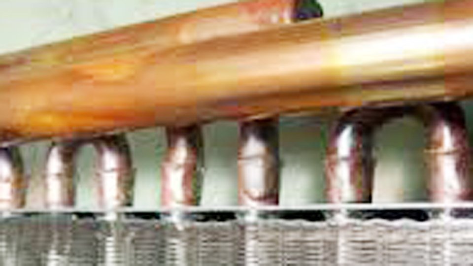
Image by msiautomation
Why HVAC Systems Demand Brazed Joints Over Soldered Connections
Brazed joints deliver shear strength typically three times higher than soldered ones because the filler metal alloys directly with the copper matrix rather than relying on lower-temperature tin-based bonding.
Mechanical Strength and Pressure Resistance
Soldered connections using 95/5 or lead-free alloys lose integrity above 300–400 psi under repeated pressure. Brazed joints with phosphorus-copper-silver alloys handle 1,000+ psi routinely, matching the burst ratings of ACR tubing.
In field repairs on 3/8-inch or 5/8-inch line sets, this margin prevents failures during pressure testing or system operation when liquid slugs create hydraulic shock.
Thermal Cycling Performance in Refrigerant Lines
HVAC lines experience rapid temperature changes during defrost cycles or startup. Solder softens near 400°F, while brazed joints remain stable to 1,300°F. This stability preserves capillary sealing in flared or swaged connections on rooftop units and split systems where ambient swings exceed 100°F daily.
Vibration and Long-Term Reliability Factors
Compressor vibration loosens soldered joints over 5–10 years. Brazed fillets distribute stress evenly across the joint overlap, reducing fatigue cracks. Installers report brazed line sets lasting 15–20 years in commercial applications with minimal leak rates when nitrogen purging eliminates internal contaminants that accelerate wear.
Choosing the Optimal Brazing Alloy for HVAC Copper Applications
Alloy choice balances flow characteristics, gap-filling ability, and cost while matching the copper-to-copper joints common in ACR tubing and fittings.
Sil-Fos 15 Specifications and Field Advantages
Sil-Fos 15 (15% silver, 5% phosphorus, 80% copper) remains the industry standard for HVAC. It has a solidus of 1,190°F and liquidus of 1,300°F, with a wide melting range that allows controlled flow into gaps up to 0.008 inches.
The phosphorus acts as a built-in deoxidizer, eliminating flux on clean copper and preventing oxide formation during heating. Its higher silver content produces stronger, more ductile joints than lower-silver options and forms reliable fillets that inspectors accept without rework.
Sil-Fos 5 vs Higher Silver Alternatives
Sil-Fos 5 (5% silver, 6% phosphorus) flows more readily at 1,325°F but liquates if heated slowly, making it suitable only for tight factory-fit joints under 0.005 inches.
For repair work with imperfect fits or when brazing to brass valves, switch to 45% silver alloys with flux—the extra silver improves wetting on dissimilar metals but raises material cost by 40%. Avoid phosphorus-bearing rods on steel or nickel because they form brittle intermetallics.
Flux Requirements for Copper-to-Copper and Dissimilar Metals
On clean copper-to-copper, skip flux entirely with Sil-Fos alloys to prevent residue inside lines. For brass fittings or oxidized repair tubing, apply a thin borax-based white flux only to the male tube end and revolve the fitting once for even coverage. Excess flux inside refrigeration circuits creates sludge when mixed with POE oils.
| Alloy | Silver % | Solidus (°F) | Liquidus (°F) | Best Use Case | Flux Needed (Cu-Cu) |
|---|---|---|---|---|---|
| Sil-Fos 15 | 15 | 1,190 | 1,300 | General HVAC line sets | No |
| Sil-Fos 5 | 5 | 1,190 | 1,495 | Tight factory joints | No |
| 45% Silver | 45 | 1,145 | 1,370 | Copper-to-brass/steel repairs | Yes |
Torch Selection and Flame Setup for Effective Brazing
Torch choice affects heat distribution and portability on rooftops or in attics where space limits cylinder size.
Air-Acetylene Systems for Typical Line Sets
Air-acetylene torches with swirl tips (TurboTorch style) reach 2,400°F and suffice for 1/4-inch to 7/8-inch ACR tubing. Set delivery pressure at 14–15 psi on tanks with gauges or open the regulator fully on preset models.
A #2 or #3 tip provides even heating without the burn-through risk of oxy setups. These rigs weigh less and eliminate oxygen cylinder handling, making them standard for residential and light commercial work.
Oxy-Acetylene Configurations for Demanding Jobs
Oxy-acetylene delivers 4,700°F at the cone for faster heating on larger 1-1/4-inch lines or cold ambient conditions. Use a neutral or slightly carburizing flame (1-inch blue cone) and #2 tip at 5 psi acetylene / 5 psi oxygen for 1/2-inch lines. The higher heat requires faster torch movement to avoid melting the base copper at 1,984°F.
Regulator Settings and Tip Sizing Guidelines
Match tip size to pipe diameter: #1–#2 for 1/4–5/8 inch, #3–#4 for 7/8–1-1/4 inch. Always oscillate the flame in small circles rather than dwelling. In cold shops below 40°F, preheat the joint area 4–6 inches away to drive off moisture before focusing on the joint.
Pipe and Fitting Preparation Standards That Ensure Capillary Success
Joint preparation accounts for 70% of braze success; rushed cleaning leads to voids visible only after pressure testing.
Cutting, Deburring, and Dimensional Accuracy
Cut tubing square with a sharp wheel cutter—never a hacksaw unless using a fixture. Deburr inside and outside with a reamer or file to remove all raised edges that block filler flow. For out-of-round tubing, use a sizing tool to restore roundness and maintain the 0.002–0.006-inch ideal capillary gap.
Surface Cleaning Protocols for Oxide-Free Joints
Abrade mating surfaces to bright copper using emery cloth or stainless wire brush until no dark oxide or oil remains. Wipe with a dry cloth to remove emery dust.
For heavily oxidized repair sections, a brief mild acid soak followed by neutralization and drying restores wettability. Clean before cutting when possible to avoid pushing debris inside sealed ACR lines.
Assembly Fit-Up and Gap Control
Insert the tube fully into the fitting with 1/4-inch minimum overlap. Support the assembly to prevent movement until the filler solidifies. Gaps larger than 0.008 inches reduce capillary action; smaller than 0.002 inches starve the joint of filler. Dry-fit first and adjust swages if needed.
Implementing Nitrogen Purging to Eliminate Internal Scale
Internal oxidation creates cupric oxide scale that flakes into the refrigerant stream, clogging TXVs and reversing valves—especially with HFC refrigerants and POE oils that scrub tube walls.
Setup and Flow Rate Decisions for Refrigeration Lines
Connect a regulator hose to a Schrader port (core removed) or open line end. Flow dry nitrogen at 2–3 CFH or 1.5–2 psi—low enough to feel slight flow on the back of the hand at the exit but not enough to pressurize and cool the joint. Cap the far end with a small vent hole. Start flow before heating and continue until the joint cools below 500°F.
Timing and Verification During Multi-Joint Brazing
Brazed hottest joints first in a line set to maintain purge continuity. After each joint, confirm clean inner walls by sectioning practice pieces. Without purge, black scale appears inside; with purge, the tube remains shiny copper. This single step prevents 90% of post-install contamination issues.
Brazing Execution: Heat Application and Filler Metal Flow Control
Heating Sequence for Horizontal and Vertical Joints
Start heating the tube 1–2 inches from the fitting, then move alternately to the fitting base until both reach temperature. For horizontal joints, heat the bottom first to create a dam as filler solidifies.
For vertical joints, heat the tube end first so gravity assists upward flow into the fitting. Keep the torch in constant short motion to maintain uniform heat.
Temperature Indicators and Rod Feeding Technique
Watch for dull red color (approximately 1,100–1,200°F) on the copper and flux (if used) turning from bubbling to clear, watery appearance.
Touch the rod to the joint edge only after the base metal reaches this point—the filler melts from joint heat, not the flame. Feed steadily to fill the capillary without excess fillet. Withdraw heat once a complete ring appears around the joint.
Cooling and Post-Heat Management
Allow natural air cooling while maintaining nitrogen flow and joint support. Quenching risks cracking; rapid cooling also traps stresses. Remove flux residue immediately with a wet brush or quench once solid to enable visual inspection and pressure testing.
Verifying Braze Quality Without Destructive Testing
Visual Inspection Criteria
A successful braze shows a smooth, concave fillet completely encircling the joint with no voids or porosity. The filler should appear shiny silver-gray, not dull or blistered. Uneven fillets signal poor heat distribution.
Pressure Testing Protocols for HVAC Lines
Pressurize with dry nitrogen to 300–500 psi (per manufacturer spec) and hold for 15–30 minutes while checking with soap solution. No bubbles means the joint passes. Follow with evacuation to 500 microns before charging to confirm system integrity.
Real-world Application Insight
Technicians who standardize on Sil-Fos 15, nitrogen at 2–3 CFH, and neutral-flame air-acetylene setups achieve first-pass leak-free rates above 95% on line sets. These choices directly cut refrigerant loss and compressor damage while meeting EPA and manufacturer requirements for warranty work.
The pro-level insight: fillet geometry serves as a real-time indicator of capillary integrity—perfectly uniform fillets correlate to zero micro-leak paths under 410A pressures, turning every braze into a predictive maintenance data point rather than a potential failure point.
FAQs
Why must nitrogen be flowed during HVAC copper pipe brazing?
Nitrogen displaces oxygen inside the tube, preventing black cupric oxide scale that flakes off and clogs TXVs, filter-driers, and capillary tubes once the system runs with POE oils.
Is flux necessary when using Sil-Fos rods on clean copper?
No. The phosphorus in Sil-Fos 5 and 15 self-fluxes clean copper-to-copper joints. Apply flux only when joining to brass fittings or oxidized repair tubing.
What torch flame adjustment prevents oxidation during brazing?
Use a neutral or slightly carburizing flame on oxy-acetylene (well-defined blue cone) or the manufacturer-recommended setting on air-acetylene swirl tips. Avoid oxidizing flames that blacken the copper surface.
How do you determine if a brazed HVAC joint will hold under system pressure?
Visually confirm a complete, shiny fillet with no voids, then pressure test with nitrogen to 300–500 psi and hold while checking for leaks with soap solution. No pressure drop equals acceptance.

Hi, I’m Zachary Ford. I’m passionate about welding and dedicated to helping both beginners and experienced welders make informed decisions. I research, test, and write about welding helmets, welding machines, safety equipment, and essential workshop tools. My goal is to provide honest reviews, practical buying guides, and easy-to-follow tutorials that help you weld more safely, work more efficiently, and choose the right gear with confidence.