Choosing between fillet weld vs groove weld directly affects joint strength, penetration profile, heat input, and inspection acceptance. The wrong selection can lead to incomplete fusion, excess distortion, failed bend tests, or unnecessary machining and rework.
Fillet welds are faster and more economical for many T-, lap-, and corner joints, but they may not achieve the root penetration or load capacity that groove welds provide in full-strength structural connections.
Groove welds, however, demand tighter fit-up, higher amperage control, and often bevel prep, which increases time and cost.
Understanding when each weld type is mechanically appropriate prevents over-welding, under-welding, and rejected weldments. The key distinctions below clarify performance limits, efficiency trade-offs, and practical selection criteria used in real fabrication and code-qualified work.
Defining Fillet Welds: Characteristics and Mechanics
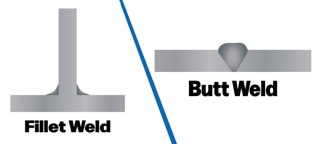
Fillet welds create a bond between two surfaces typically positioned at 90 degrees, though they can accommodate angles from 60 to 135 degrees in certain setups.
The weld metal fills the corner formed by the intersection, resulting in a concave or convex profile depending on travel speed and heat input.
In AWS D1.1 standards, fillet welds are classified by leg size, where each leg measures from the root to the toe, ensuring uniform stress distribution.
Mechanically, fillet welds rely on shear strength rather than tensile strength, making them suitable for connections where forces act parallel to the joint.
Penetration depth averages 20-30% of the base metal thickness in single-pass applications, influenced by electrode diameter and amperage.
For example, using a 1/8-inch E7018 rod at 100-140 amps DCEN provides stable arc control with minimal spatter, depositing weld metal at rates of 2-4 pounds per hour.
Joint preparation for fillet welds is straightforward: clean surfaces to remove mill scale or rust, and maintain a root gap under 1/16 inch to prevent burn-through. In vertical positions, uphill weaving techniques stabilize the molten pool, reducing undercut risks.
Material compatibility extends to carbon steels, stainless alloys, and aluminum, though aluminum requires AC polarity with helium-argon mixes for better cleaning action.
Defining Groove Welds: Characteristics and Mechanics
Groove welds involve beveling the edges of the base metal to form a V, U, J, or double-sided groove, allowing full or partial penetration through the joint thickness. This configuration enables multilayer passes to build up weld metal, achieving fusion depths up to 100% in thick plates.
Per ASME Section IX, groove welds are specified by groove angle—typically 30-45 degrees for single-V grooves—and root face dimensions to control heat-affected zone (HAZ) size.
Strength in groove welds derives from tensile and compressive properties, with fusion zones exhibiting higher yield strengths when properly back-gouged and rewelded.
Amperage settings vary by process: in SMAW, a 5/32-inch E6010 rod at 120-180 amps DCEP offers deep penetration with fast-freeze slag, ideal for root passes.
Deposition rates can reach 3-5 pounds per hour in GMAW setups using 0.035-inch ER70S-6 wire at 180-220 amps with 75/25 argon-CO2 shielding.
Preparation demands precision: bevel edges using plasma cutters or grinders to ensure consistent groove geometry, and preheat thicker materials (over 1 inch) to 150-250°F to mitigate cracking in high-carbon steels.
Positional welding favors flat or horizontal orientations, though overhead groove welds require short-circuit transfer modes in MIG to manage slag flow.
Compatibility includes high-strength low-alloy (HSLA) steels and nickel-based alloys, where polarity shifts to DCEP enhance arc stability.
Key Performance Differences: Strength, Penetration, and Efficiency
Comparing fillet and groove welds reveals stark contrasts in mechanical performance. Fillet welds provide shear strength of 60-70 ksi in standard carbon steel applications, but their partial penetration limits them to 50-70% of the joint’s full capacity.
Groove welds, with full penetration, achieve tensile strengths exceeding 80 ksi, making them superior for cyclic loading in bridges or pressure vessels.
Penetration behavior differs significantly: fillets average 0.125-0.25 inches deep in a single pass, while grooves allow 0.5-1 inch or more through multi-pass techniques. This translates to better fatigue resistance in grooves, with endurance limits 20-30% higher under repeated stress.
Arc characteristics also vary—fillets tolerate wider voltage fluctuations (18-24V in GMAW) for forgiving operation, whereas grooves require tighter controls (22-28V) to avoid lack-of-fusion defects.
Efficiency metrics highlight fillets’ advantages in setup time: preparation takes 5-10 minutes per joint versus 20-40 for grooves. However, grooves offer higher deposition rates in production environments, reducing overall labor by 15-25% on thick sections.
Slag behavior in SMAW favors grooves with easy-removal fluxes like E7018, minimizing interpass cleaning time compared to fillets’ occasional stubborn slag.
| Aspect | Fillet Weld | Groove Weld |
|---|---|---|
| Penetration Depth | 20-30% of thickness | Up to 100% |
| Strength Type | Primarily shear (60-70 ksi) | Tensile/compressive (80+ ksi) |
| Preparation Time | 5-10 min/joint | 20-40 min/joint |
| Deposition Rate (SMAW) | 2-4 lb/hr | 3-5 lb/hr |
| Fatigue Resistance | Moderate (endurance limit ~40 ksi) | High (endurance limit ~50-60 ksi) |
Travel speed influences both: fillets perform at 8-12 inches per minute to avoid convexity issues, while grooves demand slower 4-8 ipm for proper sidewall fusion. Material thickness thresholds further differentiate them—fillets suit plates under 0.5 inches, beyond which grooves prevent distortion from uneven heating.
Applications in Real-World Fabrication
Fillet welds dominate in non-critical structures like furniture frames, automotive chassis reinforcements, and light-duty brackets, where quick assembly outweighs maximum strength. In a typical U.S. shop, they’re applied in lap joints for sheet metal enclosures, leveraging their adaptability to out-of-position welding.
For instance, in pipeline repairs, fillets secure patches without full disassembly, maintaining operational uptime.
Groove welds excel in load-bearing scenarios such as beam-to-column connections in buildings or weld necks in pressure piping systems. They ensure compliance with API 1104 standards for oil and gas infrastructure, where full penetration resists internal pressures up to 10,000 psi. In heavy equipment manufacturing, grooves join thick flanges, providing the ductility needed for impact loads.
Decision factors include cost: fillets reduce filler metal use by 30-50% compared to grooves, ideal for budget-conscious hobbyists. However, for code-stamped vessels under ASME Boiler and Pressure Vessel Code, grooves are mandatory to achieve radiographic-quality welds.
Position usability tips the scale—fillets handle vertical and overhead better due to less molten pool volume, while grooves often require fixtures for stability.
In mixed applications, hybrid approaches emerge: use fillets for tacking before groove welding high-stress joints, combining speed with strength.
Joint Preparation and Welding Techniques
Effective joint preparation separates reliable welds from failures. For fillets, surface cleaning with wire brushes suffices, but grooves require beveling to 37.5 degrees for optimal access, followed by root opening of 1/16-1/8 inch to facilitate penetration without bridging.
Technique variations optimize outcomes. In fillets, stringer beads at 10-15 degree electrode angles ensure even leg sizes, while weaving in grooves (up to 1/2 inch wide) fills the cavity uniformly.
Polarity recommendations: DCEN for fillets in SMAW to concentrate heat in the electrode, versus DCEP for grooves to drive heat into the base for deeper fusion.
Amperage by rod diameter guides precision—3/32-inch rods at 70-100 amps suit thin fillets, escalating to 5/32-inch at 140-200 amps for groove root passes. Electrode classification matters: E6013 for smooth fillets with low hydrogen needs, contrasted with E7018 for grooves demanding low-hydrogen deposits to prevent cracking in quench-sensitive steels.
Common failure causes stem from inadequate preparation: in fillets, excessive gaps lead to incomplete fusion; in grooves, improper back-gouging traps slag inclusions. Travel speed adjustments mitigate this—faster in fillets (10 ipm) controls heat input, slower in grooves (6 ipm) ensures sidewall wetting.
One practical insight from shop experience: preheating to 200°F in humid environments reduces hydrogen-induced cracking in both weld types, especially on A36 steel.
Challenges and Mitigation Strategies
Weld distortion poses a challenge in both types, but grooves amplify it due to higher heat inputs. Mitigation involves sequenced welding: alternate sides in grooves to balance shrinkage forces, or use clamps in fillets to hold alignment.
Porosity arises from contamination—fillets are more forgiving with shielded processes, but grooves require thorough interpass cleaning. Undercut, prevalent in fillets at high amperages, is countered by pausing at toes; in grooves, it stems from steep angles, resolved with proper oscillation.
Inspection methods differ: visual checks suffice for most fillets per AWS A2.4, while grooves often need ultrasonic testing to detect subsurface defects. Cost implications favor fillets for low-volume work, but grooves justify expenses in high-stakes projects through longevity.
Another field-tested approach: in multi-pass grooves, cap passes with slightly convex profiles enhance corrosion resistance in outdoor exposures.
Selecting the Right Weld: A Decision Framework
When deciding between fillet and groove welds, prioritize load analysis: if shear forces dominate and thickness is under 3/4 inch, opt for fillets to minimize preparation. For tensile loads or thicker materials, grooves deliver the necessary penetration.
Evaluate efficiency: fillets cut cycle times by 40% in prototyping, while grooves boost long-term durability in structural applications. Material type influences choice—aluminum favors fillets for easier control, steels lean toward grooves for strength.
Budget and equipment availability matter: basic stick welders handle fillets effectively, but grooves benefit from advanced MIG setups with pulse modes for reduced spatter.
In verdict, groove welds prevail for critical integrity, but fillets offer unmatched versatility in everyday fabrication. This framework ensures selections align with performance needs without overengineering.
For an advanced insight, consider hybrid electron beam welding in high-precision grooves, achieving 95% penetration efficiency with minimal distortion on aerospace alloys—a technique gaining traction in U.S. defense contracting.
FAQ’s
What is the main strength difference between fillet and groove welds?
Fillet welds emphasize shear strength, typically 60-70 ksi, suitable for angular joints under parallel loads. Groove welds provide superior tensile strength over 80 ksi through full-thickness fusion, essential for perpendicular stress in heavy structures.
When should I choose a fillet weld over a groove weld in a DIY project?
Select fillets for quick lap or T-joints in thin materials like 1/4-inch steel, where preparation is minimal and strength requirements are moderate. Avoid grooves unless full penetration is needed to meet safety codes in load-bearing DIY frames.
How does joint preparation time compare for fillet vs groove welds?
Fillet preparation averages 5-10 minutes, focusing on cleaning. Groove welds require 20-40 minutes for beveling and fitting, but this investment yields deeper penetration in thick sections.
What electrode is best for groove welds in carbon steel?
E7018 low-hydrogen electrodes at 120-180 amps DCEP excel for groove fills, offering clean slag removal and crack resistance. Pair with E6010 for root passes to ensure fast-freeze characteristics.
Can fillet welds achieve the same penetration as groove welds?
No, fillets max at 30% penetration without modification, while grooves reach 100%. For deeper needs, convert to partial-penetration grooves by adding bevels.