The Miller Bobcat series represents a line of engine-driven welders designed for robust field performance, delivering reliable power for stick, MIG, and auxiliary applications. Battery removal from a Miller Bobcat welder becomes essential during routine maintenance, replacement due to diminished capacity, or storage preparation.
This procedure ensures uninterrupted starting capability, critical for operations where engine reliability directly impacts weld quality and productivity. Neglecting battery issues can lead to failed starts, reduced arc stability, and increased downtime in fabrication environments.
Proper execution maintains the welder’s electrical integrity, adhering to manufacturer specifications for models such as the Bobcat 225, 250, and 260.
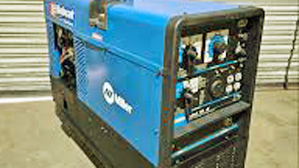
Image ig/steven_welding_shop
Role of the Battery in Miller Bobcat Welders
Miller Bobcat welders integrate a 12-volt battery system to initiate the internal combustion engine, which powers the generator for welding output. The battery supplies cranking amperage to the starter motor, enabling engine turnover at speeds sufficient for ignition—typically 200-300 RPM under load.
In EFI-equipped models like the Bobcat 250 with Kohler ECH730, the battery also supports electronic fuel injection components, demanding stable voltage to prevent system faults.
Standard battery configuration adheres to BCI Group 58 dimensions: approximately 10.1 inches long, 7.2 inches wide, and 7.9 inches high. Original equipment often specifies 430 cold cranking amps (CCA) at 0°F, with 75 amp-hours reserve capacity, ensuring reliable starts in temperatures down to -20°F.
Higher CCA ratings, up to 850, enhance performance in extreme cold without risking electrical overload, as the welder’s charging circuit regulates output at 14-15 volts.
The battery interfaces with the alternator, which recharges at 20-30 amps during operation, maintaining voltage between 12.6-12.8 volts at rest.
In carbureted variants like the Bobcat 225 with Onan engines, the system prioritizes simplicity, while EFI models incorporate safeguards against voltage spikes that could damage control modules.
Identifying When Battery Replacement is Necessary
Battery degradation in engine-driven welders manifests through measurable performance declines. Slow engine cranking, where turnover speed drops below 150 RPM, indicates insufficient CCA delivery, often due to sulfation on lead plates reducing effective capacity by 20-30%.
Voltage tests reveal failures: a rested battery reading below 12.4 volts signals deep discharge, while load testing under 300 amps for 15 seconds yielding less than 9.6 volts confirms replacement need.
Frequent no-start conditions, even after external charging, point to internal shorts or open cells, common after 3-5 years of service in high-vibration environments.
Electrolyte levels dropping below plate tops in flooded batteries accelerate corrosion, reducing lifespan by 50%. In sealed AGM types, swelling cases or leaking terminals denote overcharging from faulty regulators.
Environmental factors exacerbate issues: prolonged storage without trickle charging leads to self-discharge at 1-2% per day, dropping voltage to 11.8 volts within months. High operating temperatures above 100°F halve battery life, while vibration from engine operation loosens connections, increasing resistance by 0.1-0.5 ohms and causing intermittent failures.
Required Tools and Materials
Efficient battery removal requires precise tooling to avoid damage to welder components. Essential items include:
- 1/2-inch socket wrench for rear panel bolts and battery holddown.
- 10mm or 13mm open-end wrench for cable terminals.
- Phillips screwdriver for access panels on select models.
- Torque wrench calibrated to 5-7 ft-lbs for reassembly.
- Multimeter for voltage and continuity checks.
- Battery terminal cleaner or wire brush for corrosion removal.
Materials comprise a replacement battery matching Group 58 specifications, dielectric grease for terminal protection, and baking soda solution (1:10 ratio with water) for neutralization.
PPE consists of nitrile gloves resistant to acid, safety goggles meeting ANSI Z87.1 standards, and face shields for splash protection.
Safety Precautions for Battery Handling
Battery servicing poses risks of explosion, acid burns, and electrical shock. Always disconnect the negative cable first to minimize short-circuit potential, reducing arc flash risk. Wear rubber gloves rated for 1000 volts and protective eyewear to guard against sulfuric acid exposure, which can cause burns at concentrations of 1.265 specific gravity.
Avoid sparks near batteries, as hydrogen gas evolves at 0.1-0.5 liters per hour during charging, ignitable at 4% concentration. Stop the engine prior to disconnection, preventing alternator diode damage from load dumps exceeding 20 volts. For EFI models, never disconnect while running, as this induces voltage transients up to 100 volts, risking ECU failure.
Observe polarity: positive terminal connects first during installation. Charge batteries externally with the negative cable detached, using chargers limited to 5-10 amps to prevent gassing.
Flush skin or eyes with water for 15 minutes if contacted by electrolyte, and replace cracked casings immediately to avoid leaks.
Step-by-Step Battery Removal Procedure
This procedure applies to Bobcat 225, 250, and 260 models, with minor variations in panel access. Ensure the welder is on level ground, engine off, and cooled.
Accessing the Battery Compartment
Locate the rear panel, secured by 6-8 bolts (1/4-20 thread, 1/2-inch head). Remove bolts counterclockwise, storing them to prevent loss. Lift the panel with integrated baffle outward, exposing the battery tray. On Bobcat 260 models, open side access doors first for partial visibility, but full removal requires rear panel detachment.
Inspect for pinched fuel vent hoses or cables during panel removal, as compression can restrict flow by 20-30%, leading to vapor lock.
Disconnecting the Battery Cables
Measure battery voltage prior to disconnection; readings below 12 volts indicate pre-existing issues. Loosen the negative terminal clamp first using a 10mm wrench, turning counterclockwise 2-3 turns. Wiggle and lift the cable free, securing it away from the post to prevent accidental contact.
Repeat for the positive terminal, noting any corrosion buildup exceeding 0.5mm thickness, which increases resistance and reduces cranking amps by 10-15%. Clean terminals with a wire brush, achieving a resistance below 0.01 ohms.
Removing the Battery Holddown
The holddown bracket secures the battery against vibration, fastened by two 3/8-inch bolts torqued to 4-6 ft-lbs. Remove bolts, then lift the bracket upward. On models with EFI, route cables carefully to avoid straining harnesses connected to the voltage regulator.
Extracting the Battery
Grasp the battery by integrated handles or sides, lifting straight up with a force not exceeding 50 lbs to avoid case distortion. Weight typically ranges 25-35 lbs for Group 58 units. Inspect the tray for acid residue, neutralizing with baking soda solution to prevent corrosion propagation at 0.1mm per year.
Selecting a Replacement Battery
Replacement batteries must meet or exceed original specifications for compatibility. Prioritize BCI Group 58 with minimum 430 CCA, though 550-850 CCA variants improve cold-start reliability by 20-30% without overloading the 20-amp alternator.
| Model | Battery Group | Minimum CCA | Reserve Capacity (Ah) | Voltage | Recommended Type |
|---|---|---|---|---|---|
| Bobcat 225 | 58 | 430 | 75 | 12V | Flooded Lead-Acid or AGM |
| Bobcat 250 | 58 | 550 | 85 | 12V | AGM for Vibration Resistance |
| Bobcat 260 | 58 | 580 | 90 | 12V | Maintenance-Free Sealed |
Opt for AGM batteries in high-vibration settings, offering 2-3 times the cycle life of flooded types at depths of discharge up to 50%. Ensure terminals match SAE post configuration, with positive on the right when facing the label.
Installing the New Battery
Reverse the removal sequence for installation. Position the battery in the tray, aligning terminals rearward. Secure the holddown bracket at 5 ft-lbs torque to prevent shifting under 5G forces. Connect the positive cable first, tightening to 4-6 ft-lbs, followed by negative.
Apply dielectric grease to terminals, reducing oxidation by 80%. For EFI models, verify no cable pinching occurs during panel reinstallation, as this can induce shorts drawing 1-2 amps continuously.
Post-Installation Testing and Maintenance
Post-installation, crank the engine to confirm starter engagement within 2-3 seconds. Measure charging voltage at 3000 RPM: 13.8-14.5 volts indicates proper alternator function. Load test the battery at 300 amps, ensuring voltage holds above 9.6 volts.
Maintenance includes cleaning terminals every 100 hours, removing corrosion to maintain conductance. Recharge stored batteries every 3 months at 2 amps to counteract 1% daily self-discharge. Monitor electrolyte in flooded units, topping with distilled water to 0.25 inches above plates.
Troubleshooting Common Battery-Related Issues
Persistent no-start after replacement often stems from loose connections increasing resistance to 0.2 ohms, dropping effective voltage by 1-2 volts. Test cable continuity: resistance exceeding 0.05 ohms warrants replacement.
Over-discharge between uses indicates parasitic draws from faulty idler solenoids, consuming 0.1-0.5 amps. Isolate by disconnecting accessories sequentially. Charging failures trace to alternator diodes, verifiable by AC ripple under 0.5 volts at output.
In cold climates, insufficient CCA manifests as clicking starters; upgrade to 700+ CCA resolves 90% of cases. EFI fault codes post-installation signal polarity reversal—recheck connections immediately.
Conclusion
Adhering to precise battery removal and replacement protocols in Miller Bobcat welders safeguards against operational interruptions, preserving engine start reliability essential for consistent weld deposition. Regular voltage checks and terminal maintenance extend service intervals, minimizing unplanned downtime in demanding fabrication tasks.
For prevention, integrate battery load testing into 200-hour service cycles to detect capacity loss early, avoiding field failures. As an advanced insight, calibrate travel speed during battery-impacted starts to maintain arc stability at 18-22 inches per minute, compensating for voltage fluctuations in critical joints.
FAQs
How often should the battery be inspected in a Miller Bobcat welder?
Inspect every 100 hours: clean terminals, check voltage above 12.6 volts, and verify secure holddown to counter vibration effects.
What battery type is best for cold-weather operations?
AGM Group 58 with 700+ CCA, providing 25% more starting power at -20°F compared to standard flooded units.
Can a higher CCA battery damage the welder?
No, as the charging system limits output; higher CCA enhances reliability without overload.
Why does the engine crank slowly after storage?
Self-discharge reduces capacity; recharge at 5 amps for 30 minutes prior to use.
What if the welder shows EFI faults after battery replacement?
Verify polarity and connections; reset by disconnecting battery for 5 minutes to clear transient codes.