Incorrect parameter selection is a leading cause of poor stainless weld quality, and a reliable
mig welding stainless steel settings chart is the fastest way to prevent it. Stainless requires tighter control than mild steel because voltage, wire feed speed, and shielding gas balance directly affect penetration, chromium burn-off, porosity, and distortion.
Even small deviations can destabilize the arc or produce sugaring and weak fusion that fail inspection. A properly referenced chart translates material thickness and wire diameter into usable machine settings, removing guesswork and reducing costly test passes.
This matters in real fabrication environments where time, filler metal, and rework expenses add up quickly. Understanding how to read and apply these settings ensures consistent bead profile, stable transfer, and
Fundamentals of MIG Welding Stainless Steel
Stainless steel alloys, particularly austenitic grades like 304 and 316, exhibit chromium content above 10.5% for corrosion resistance, but this composition increases susceptibility to carbide precipitation if heat input exceeds optimal levels.
MIG welding, or gas metal arc welding (GMAW), employs a continuous filler wire as the electrode, with shielding gas protecting the molten pool from atmospheric contamination.
Material Properties Impacting Welding Parameters
Stainless steel conducts heat at roughly half the rate of carbon steel, leading to localized heat buildup and potential warping.
Its coefficient of thermal expansion is 50% higher, amplifying distortion risks. Electrical resistivity is elevated, resulting in lower amperage for equivalent wire feed speeds.
These factors require reduced current densities—typically 10-15% below mild steel equivalents—to prevent burn-through while maintaining fusion. Parameter selection must account for these properties to achieve balanced penetration and bead profile.
Consumables Selection
Selecting appropriate consumables ensures compatibility with base metal chemistry and welding mode.
Filler Wire Types and Diameters
Use ER308L or ER316L wires for austenitic stainless steels to match corrosion resistance and minimize carbon migration. Silicon-enhanced variants like ER308LSi improve puddle fluidity.
Wire diameters range from 0.023 to 0.045 inches, selected based on thickness: smaller diameters for thin gauges to limit heat input, larger for heavier sections to increase deposition. Avoid overmatching filler strength unless specified for high-stress applications.
Shielding Gas Mixtures
For short circuit transfer, employ tri-mix (90% He / 7.5% Ar / 2.5% CO2) to stabilize the arc and flatten the bead profile. In spray transfer, 98% Ar / 2% O2 promotes wetting and reduces spatter.
Avoid high CO2 blends, as they introduce carbon and compromise corrosion properties. Gas flow rates of 20-40 cfh maintain coverage without turbulence.
Machine Configuration
Proper setup optimizes power delivery and arc characteristics.
Polarity and Power Source
Direct current electrode positive (DCEP) is standard for MIG stainless steel welding, providing deeper penetration and stable droplet transfer.
Constant voltage power sources are preferred for consistent arc length. For compact welders, initiate with mild steel settings and adjust upward in voltage while monitoring amperage draw.
Parameter Settings for Short Circuit Transfer
Short circuit transfer suits thin materials (under 0.125 inches) and out-of-position welding, characterized by low heat input and controlled spatter. The following chart details parameters for DCEP polarity using tri-mix gas.
| Wire Diameter (in) | Wire Speed (ipm) | Amps | Volts | Electrical Stick-out (in) | Gas Flow (cfh) |
|---|---|---|---|---|---|
| 0.023 | 180-400 | 30-85 | 14-19 | 3/8-1/2 | 20-25 |
| 0.030 | 150-350 | 45-125 | 15-20 | 3/8-1/2 | 20-25 |
| 0.035 | 120-330 | 60-150 | 16-22 | 3/8-1/2 | 20-30 |
| 0.045 | 100-280 | 90-210 | 17-22 | 3/8-1/2 | 25-30 |
These ranges allow fine-tuning for arc stability; higher speeds increase deposition but risk incomplete fusion if voltage is insufficient.
Parameter Settings for Spray Transfer
Spray transfer is ideal for thicker sections (over 0.125 inches) in flat or horizontal positions, offering high deposition rates and smooth bead appearance. Use 98% Ar / 2% O2 gas for optimal performance.
| Wire Diameter (in) | Wire Speed (ipm) | Amps | Volts | Electrical Stick-out (in) | Gas Flow (cfh) |
|---|---|---|---|---|---|
| 0.030 | 280-600 | 160-220 | 24-28 | 3/8-1/2 | 25-35 |
| 0.035 | 250-470 | 170-295 | 23-29 | 1/2-3/4 | 25-35 |
| 0.045 | 200-385 | 195-360 | 24-30 | 1/2-3/4 | 30-35 |
| 1/16 | 110-200 | 210-380 | 25-31 | 1/2-3/4 | 35-40 |
For 904L alloys, adjust to 70% Ar / 30% He at 165-220 amps and 25-30 volts for 0.045-inch wire to enhance fluidity.
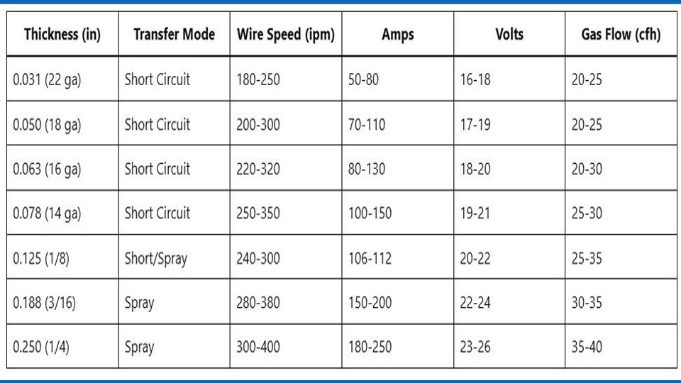
Parameter Adjustment for Specific Thicknesses
Base parameter selection on thickness to balance penetration and heat input. For stainless steel, amperage approximates 1 amp per 0.001 inch, reduced 10-15% from mild steel due to resistivity. The table below provides guidelines, assuming 0.035-inch wire and tri-mix for short circuit or Ar/O2 for spray.
| Thickness (in) | Transfer Mode | Wire Speed (ipm) | Amps | Volts | Gas Flow (cfh) |
|---|---|---|---|---|---|
| 0.031 (22 ga) | Short Circuit | 180-250 | 50-80 | 16-18 | 20-25 |
| 0.050 (18 ga) | Short Circuit | 200-300 | 70-110 | 17-19 | 20-25 |
| 0.063 (16 ga) | Short Circuit | 220-320 | 80-130 | 18-20 | 20-30 |
| 0.078 (14 ga) | Short Circuit | 250-350 | 100-150 | 19-21 | 25-30 |
| 0.125 (1/8) | Short/Spray | 240-300 | 106-112 | 20-22 | 25-35 |
| 0.188 (3/16) | Spray | 280-380 | 150-200 | 22-24 | 30-35 |
| 0.250 (1/4) | Spray | 300-400 | 180-250 | 23-26 | 35-40 |
Adjust from mild steel baselines: increase wire speed slightly for equivalent thickness to compensate for lower current, and elevate voltage by 1-2 volts for better wetting. Test on scrap to verify fusion.
Technique Considerations
Execution influences parameter effectiveness.
Joint Preparation
Clean surfaces to remove oxides using stainless steel brushes or chemical pickling. Bevel edges on thicknesses over 0.125 inches at 30-45 degrees for full penetration. Maintain 0.040-0.060-inch root gaps for fillet welds to allow gas escape and reduce porosity.
Travel Speed and Angle
Travel speeds of 8-15 inches per minute control heat input; slower speeds risk overheating, faster may cause lack of fusion. Use a 10-15 degree push angle for spray transfer to direct arc force, ensuring even bead distribution. In short circuit, a drag angle minimizes spatter.
Quality Control and Common Defects
Monitor welds for defects tied to parameter mismatches.
Penetration and Fusion Issues
Insufficient amperage yields shallow penetration; increase by 10-20 amps while observing arc sound for crisp transfer. Overly high voltage causes undercutting—reduce to flatten the bead.
Distortion Management
Stainless steel’s high expansion demands sequenced welding and clamping. Limit interpass temperatures to 300°F to prevent sensitization. Backstepping techniques distribute heat evenly on long seams.
In practice, preheating to 200°F for thicknesses over 0.250 inches stabilizes arc initiation without compromising properties, based on shop trials with 316L fabrications.
Performance Summary
Optimal MIG welding of stainless steel hinges on quantified parameters tailored to transfer mode and thickness, as outlined in the settings charts. Short circuit excels in thin gauges for controlled heat, while spray enhances efficiency on heavier stock through higher deposition.
Adjustments for material resistivity ensure arc stability and weld integrity, directly supporting fabrication demands in corrosive environments. Prioritize testing and calibration to machine specifics for repeatable results.
In pulsed MIG variants, synchronize pulse frequency to wire feed speed for 20-30% improved penetration control on austenitic grades, reducing spatter by 50% in vertical positions without sacrificing speed.
What voltage and wire speed for MIG welding 1/8-inch stainless steel?
For 0.125-inch thickness, use 20-22 volts and 240-300 ipm with 0.035-inch wire in short circuit or transitional spray, adjusting amperage to 106-112 for fusion without burn-through.
Recommended shielding gas for MIG stainless steel?
Tri-mix (90% He / 7.5% Ar / 2.5% CO2) for short circuit; 98% Ar / 2% O2 for spray to optimize wetting and minimize oxidation.
How to adjust MIG settings from mild steel to stainless?
Increase wire feed speed slightly for lower current draw, add 1-2 volts for better puddle flow, and verify on test pieces.
MIG wire diameter for thin stainless sheet?
Select 0.023-0.030 inches for gauges under 0.063 inches to limit heat input and prevent warping.
Causes of porosity in stainless MIG welds?
Inadequate gas coverage (under 20 cfh) or contaminated surfaces; ensure flow rates and pre-clean thoroughly.

Hi, I’m Zachary Ford. I’m passionate about welding and dedicated to helping both beginners and experienced welders make informed decisions. I research, test, and write about welding helmets, welding machines, safety equipment, and essential workshop tools. My goal is to provide honest reviews, practical buying guides, and easy-to-follow tutorials that help you weld more safely, work more efficiently, and choose the right gear with confidence.