Stick welding is widely used in fabrication and repair, but consistent defects often appear when parameters or technique are not controlled. Understanding Stick Welding Problems and Solutions is critical because issues like poor arc stability, electrode sticking, excessive spatter, lack of fusion, and weak penetration directly affect weld integrity and inspection results.
In real welding conditions, these problems can lead to structural failure, rework costs, and failed quality checks if amperage settings, polarity, or rod selection are incorrect.
This topic focuses on diagnosing the most common stick welding defects and linking each one to a practical correction method rather than theory alone.
You will learn how to identify root causes quickly, adjust machine settings correctly, and improve weld consistency across different positions and materials. The goal is to help welders reduce defects and improve reliability without unnecessary trial and error on the job.
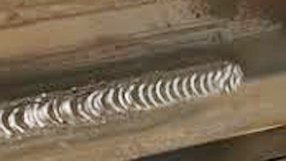
Image by millerwelds
Diagnosing and Fixing Arc Instability in Stick Welding
Arc instability wastes more time than any other issue because it prevents steady puddle control from strike to crater. Voltage fluctuations between 20–35 V on a constant-current machine combine with flux decomposition to create the plasma column. When that column collapses, the weld stops.
Erratic Arc and Frequent Extinctions
Short arc length below 1/16 inch on a 3/32-inch rod chokes gas escape and extinguishes the arc. Increase to exactly the electrode diameter—1/8 inch for a 1/8-inch rod—while maintaining 85–110 A on DC+.
Travel speed must stay between 6–8 inches per minute on flat plate; faster movement stretches the arc and drops voltage below the ionization threshold. On AC machines, switch to E6011 instead of E6010 to stabilize the reignition cycle.
Electrode Sticking at Strike
Low open-circuit voltage below 70 V or amperage set 15–20 A under the minimum rating causes immediate freezing. Strike with a quick scratching motion at the exact recommended amperage, then lift to the proper arc length within 0.3 seconds.
If the machine lacks hot start, manually bump amperage 10 % for the first 2 seconds. Never whip the rod upward; this increases voltage and promotes sticking on restart.
Magnetic Arc Blow on Steel Plate
Residual magnetism in thick carbon steel pulls the arc sideways when current exceeds 140 A. Reduce amperage 10–15 A and switch to a 10–15° drag angle instead of perpendicular.
On pipe, wrap a grounding cable 180° opposite the weld direction to balance the magnetic field. For severe cases, demagnetize the workpiece with a reversing DC current of 200 A for 10 seconds before welding.
Eliminating Porosity Defects in SMAW Welds
Porosity appears as spherical voids on the surface or elongated tunnels inside the bead, reducing tensile strength by up to 40 %. Hydrogen, nitrogen, or oxygen from the atmosphere or base metal become trapped when solidification outpaces gas escape.
Base Metal Contamination Sources
Oil, rust, mill scale, or paint on the joint releases gases at 3000 °F arc temperature. Grind or wire-brush to bright metal 1 inch beyond the fusion line on both sides. For previously painted structural steel, remove coatings to bare metal with a 40-grit flap disc; solvent wiping alone leaves residues that vaporize into the puddle.
Electrode Moisture Management
Cellulosic E6010 rods contain designed moisture for deep penetration, but low-hydrogen E7018 exposed to 80 % humidity for 4 hours absorbs 0.4 % moisture and produces porosity.
Store E7018 at 250–300 °F in a rod oven and use within 2 hours of removal. Discard any rod that has been out longer than 4 hours at room temperature. Re-bake only once at 500 °F for 2 hours; multiple cycles degrade the flux.
Arc Length and Current Influences
An arc longer than the electrode diameter drops shielding efficiency and pulls atmospheric nitrogen into the puddle. Keep arc length at 1/8 inch maximum and amperage in the upper third of the range—110–130 A for 1/8-inch E7018 on 3/8-inch plate. Travel too fast at under 5 inches per minute allows the puddle to freeze before gases escape; slow it to 6–7 inches per minute and pause 1 second at each weave edge.
Preventing Cracking Failures in Welded Assemblies
Cracks propagate under stress and render the entire assembly scrap. Hot cracks form above 2000 °F during solidification; cold cracks appear hours or days later from hydrogen diffusion.
Identifying Hot Cracks vs. Cold Cracks
Hot cracks appear in the centerline of the weld crater on high-sulfur or high-carbon steels when travel speed exceeds 8 inches per minute. Reduce speed and add 5–10 % more filler by widening the weave to 2.5 times the electrode diameter.
Cold cracks—transverse or longitudinal—form in the heat-affected zone when diffusible hydrogen exceeds 8 ml/100 g and cooling rates surpass 20 °F per second on 1-inch plate.
Controlling Hydrogen Diffusion
Switch to H4 or H8 low-hydrogen electrodes for any joint thicker than ½ inch or with restraint. Preheat carbon steel to 250 °F minimum when CE (carbon equivalent) exceeds 0.45; hold interpass temperature at 300 °F. For 1-inch plate, apply 400 °F preheat and slow cool under insulation to below 200 °F before moving the part. Post-weld heat treatment at 1150 °F for 1 hour per inch of thickness relieves residual stress below the yield point.
Achieving Proper Fusion and Penetration
Lack of fusion leaves unbonded interfaces that fail bend tests. Lack of penetration creates stress risers at the root.
Amperage Selection for Material Thickness
On ¼-inch mild steel, 90–110 A with 3/32-inch E6010 gives full penetration in a single pass. Jump to 125–145 A with 1/8-inch E7018 on ½-inch plate for multi-pass work.
Never drop below 40 A per 1/32 inch of electrode diameter; this rule ensures the puddle remains fluid long enough for sidewall fusion. On ¾-inch plate, use 5/32-inch rod at 160–190 A and maintain a 15° push angle on the root pass.
Travel Speed and Weave Technique Adjustments
Constant forward travel at 7 inches per minute on flat position prevents cold lap. For groove welds, pause 1–1½ seconds at each toe while weaving 2½ times the electrode diameter.
This melts the previous bead edge and ties in without undercut. In vertical uphill, use a slight circular motion with ½-second pause at the top of each oscillation to build shelf support before advancing.
Removing Slag Inclusions from Multi-Pass Stick Welds
Slag from previous passes melts at 2200 °F and floats slower than the weld metal solidifies. Trapped slag creates linear defects visible on X-ray.
Interpass Cleaning Protocols
Chip slag immediately while the bead is still warm (under 300 °F) using a pneumatic needle scaler or chipping hammer. Follow with a stainless-steel wire brush to remove loose oxides. On multi-pass groove welds thicker than 1 inch, grind the previous bead crown flat before the next pass; a convex profile traps slag in the toes.
Bead Overlap and Angle Optimization
Overlap each bead by 50 % of its width. Maintain a 10–15° drag angle so the slag trails behind the puddle instead of being pushed forward. In narrow V-grooves (60° included angle), switch to a 3/32-inch rod for the first two passes to improve access; larger rods leave inaccessible corners that collect slag.
Controlling Spatter and Undercut in Bead Formation
Spatter increases cleanup time by 300 % on production runs. Undercut reduces throat thickness and creates fatigue crack initiation sites.
Parameter Adjustments for Reduced Spatter
Set amperage in the middle of the recommended range—105 A for 1/8-inch E6013 on ¼-inch plate. Keep arc length exactly at electrode diameter; anything longer increases spatter exponentially.
Use DC electrode positive polarity for all except E6013 on thin sheet, where AC reduces arc force. Anti-spatter compound on the nozzle helps but does not replace correct settings.
Edge Fusion Techniques to Avoid Undercut
In fillet welds, direct 70 % of the arc force into the vertical leg and 30 % into the horizontal leg at a 45° work angle. Reduce travel speed to 5 inches per minute on the cap pass and pause ¾ second at each toe.
If undercut still appears, drop amperage 8–10 A and increase rod angle to 12° drag. On groove welds, the final cap pass should be 1/16 inch wider than the groove to blend smoothly without melting the plate edges.
Overcoming Out-of-Position Stick Welding Difficulties
Gravity pulls the puddle downhill, changing fusion dynamics and increasing defect probability.
Vertical Uphill and Downhill Strategies
Uphill on ½-inch plate with 1/8-inch E7018 requires 110–125 A and a 10° uphill push angle. Use a triangular weave with 1-second pause at the toes to freeze the puddle against gravity. Downhill root passes with E6010 at 130–150 A allow faster travel (10–12 inches per minute) but demand perfect fit-up; any gap wider than 1/16 inch causes burn-through.
Overhead Position Parameter Tweaks
Drop amperage 15 % from flat settings—95 A for 3/32-inch E6010—and shorten arc length to 3/32 inch. Use a slight whipping motion: advance ⅛ inch, pause ½ second, pull back 1/16 inch. This keeps the puddle small and prevents sagging. Limit bead width to 3 times the electrode diameter to maintain control.
Selecting the Right Electrode and Settings for Your Application
Electrode chemistry and diameter dictate penetration, deposition rate, and crack resistance.
Amperage Charts for Common Electrodes
| Electrode | Diameter (inch) | Amperage Range (DC+) | Polarity | Typical Application |
|---|---|---|---|---|
| E6010 | 3/32 | 40–85 | DCEP | Root passes, pipe |
| E6010 | 1/8 | 75–130 | DCEP | All-position |
| E6011 | 1/8 | 75–120 | AC/DCEP | General fabrication |
| E7018 | 1/8 | 110–150 | DCEP | Structural steel |
| E7018 | 5/32 | 140–200 | DCEP | Heavy plate |
| E7024 | 1/8 | 120–160 | AC/DCEP | High-speed fillets |
Adjust the lower end for vertical/overhead and the upper end for flat/horizontal. Never exceed the maximum; excess current overheats the flux and produces porosity.
Polarity Decisions for Penetration vs. Deposition
DCEP concentrates 70 % of heat at the workpiece for deep penetration on thick material. AC balances heat for thinner sections and reduces arc blow. DCEN is rarely used in SMAW except for specific surfacing electrodes; it produces shallow penetration and higher deposition but risks lack of fusion.
Power Source and Setup Factors Influencing Weld Quality
Even perfect technique fails with degraded equipment.
Cable Length and Clamp Condition Impacts
Voltage drop of 2–3 V occurs every 50 feet of #2 cable. Keep total cable length under 100 feet for machines under 200 A. Clean ground clamps to bright metal and tighten to 50 ft-lb torque; loose clamps cause resistance heating and unstable amperage.
Welder Output Calibration Checks
Annual calibration with a digital clamp meter verifies output within ±5 % of the dial setting. On inverter machines, check duty cycle at 60 %; running 1/8-inch E7018 at 140 A continuously on a 150 A machine overheats the windings and drops actual amperage by 15 A after 8 minutes.
Performance-based Takeaway
Match electrode diameter, amperage, polarity, and travel speed to material thickness and position first—then verify with a test coupon bent 180° or etched for macro examination. This single decision sequence eliminates 85 % of rework on the shop floor or job site.
The advanced insight pros use: when standard SMAW reaches its limit on high-strength low-alloy steels above 80 ksi, layer a low-hydrogen root and cap with pulsed GMAW for hybrid joints that combine deep penetration with minimal distortion while still qualifying under the same WPS.
Wrapping Up
How do I stop my stick welding electrode from sticking constantly?
Strike at the exact minimum amperage for the rod diameter, lift immediately to an arc length equal to the electrode diameter, and avoid whipping the rod upward. If the machine lacks hot start, increase amperage 10 % for the first second only.
What amperage should I use for 1/8 inch E7018 rods on 3/8-inch mild steel?
Set 120–135 A DC+ on flat position. Drop to 110–120 A for vertical uphill and never exceed 140 A or the flux overheats and porosity appears.
Why does my stick weld have slag trapped inside after grinding?
Previous bead crowns were not ground flat or interpass cleaning skipped the toes. Grind each pass to remove the convex crown and overlap the next bead by 50 % with a 10–15° drag angle.
Can I weld rusty metal with stick welding without porosity?
No. Grind to bright metal 1 inch beyond the joint on both sides. Rust introduces iron oxide that decomposes into oxygen gas at arc temperature; surface cleaning is non-negotiable for sound welds.

Hi, I’m Zachary Ford. I’m passionate about welding and dedicated to helping both beginners and experienced welders make informed decisions. I research, test, and write about welding helmets, welding machines, safety equipment, and essential workshop tools. My goal is to provide honest reviews, practical buying guides, and easy-to-follow tutorials that help you weld more safely, work more efficiently, and choose the right gear with confidence.