Setting up a welder incorrectly in a garage can lead to unstable arcs, inconsistent penetration, and increased risk of weld defects or electrical hazards. Understanding how to setup a welder in my garage is essential for achieving reliable weld quality while maintaining safe operating conditions.
Key factors such as proper power supply, grounding, ventilation, and machine calibration directly affect amperage stability and arc performance, especially in confined residential spaces.
In real welding conditions, poor setup often results in spatter, weak joints, or overheating equipment—issues that lead to rework and wasted materials. A correctly configured garage setup ensures consistent output, better control over heat input, and improved weld integrity across different metals and thicknesses.
This guide will help you establish a functional and safe welding environment, allowing you to operate efficiently while minimizing common setup-related problems that impact both performance and safety.
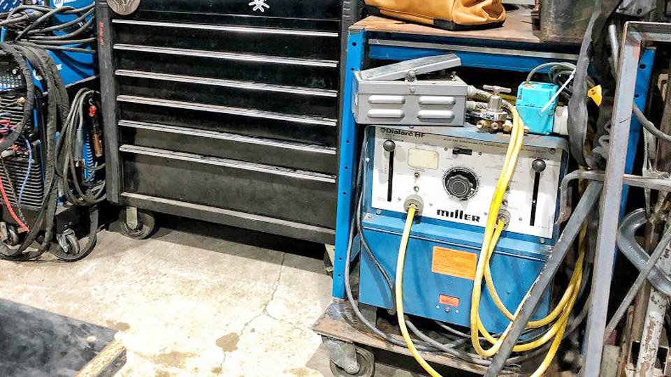
Image by thefabricator
Matching Welder Type to Garage Power Availability
Garage electrical panels rarely exceed 100–200 A total service, so welder selection must align with available dedicated circuits rather than maximum advertised output.
120-Volt Limitations for Light-Duty Applications
120 V machines draw 15–20 A at full load and top out around 90–140 A output depending on inverter efficiency. They weld 16–14 ga sheet and up to 1/8 in mild steel in short-circuit transfer without issues but lose penetration above that thickness because voltage sags under load.
Duty cycle drops to 20–30 % at peak amperage, forcing cooldown pauses on anything thicker than 0.125 in. These units suit mobile hobby work or panels where portability outweighs power, but they cannot sustain spray transfer or handle structural 3/16 in plate without multiple passes and preheat.
240-Volt Advantages for Structural Work
240 V units access 180–300 A ranges with 40–60 % duty cycles at 200 A. The doubled voltage halves current draw for the same power, reducing I²R heating in the machine and allowing thicker wire or higher deposition rates.
On 1/4 in plate, a 240 V MIG maintains stable spray transfer at 220–250 A where a 120 V unit would stall in globular mode. Voltage stability also improves arc force, producing narrower heat-affected zones and less distortion on thin-to-thick transitions common in garage chassis or bracket repairs.
Dual-Voltage Machines as Flexible Solutions
Inverter models with MVP plugs switch between 120 V and 240 V receptacles without rewiring. At 120 V they deliver 90–130 A; at 240 V they reach full 200–250 A output. This eliminates the need for immediate panel upgrades while preserving future expandability.
When the garage circuit is upgraded later, the same machine doubles its capability without repurchase. Real-world testing shows dual-voltage inverters maintain ±1 V regulation across both supplies, unlike older transformer machines that lose 3–5 V on 120 V lines.
Calculating and Upgrading Electrical Circuits for Stable Output
Voltage drop becomes the dominant performance killer once cable runs exceed 15 ft or circuits share loads with compressors and lights.
Required Breaker Sizes and Outlet Configurations
A 120 V welder rated 20 A input needs a dedicated 25–30 A breaker and NEMA 5-30R receptacle on 10 AWG copper. A 240 V machine drawing 40–50 A requires a 50 A double-pole breaker, NEMA 6-50R receptacle, and 6 AWG conductors.
These ratings provide 125 % headroom per NEC guidelines, preventing nuisance trips when the machine hits peak inrush during arc starts. Shared 15 A household circuits drop below 110 V under load, collapsing arc voltage and causing wire to stub instead of burn off cleanly.
Voltage Drop Mitigation Through Cable Sizing
Every 100 ft of 12 AWG copper on 240 V drops approximately 3.5 V at 50 A. Keeping runs under 25 ft and using 6 AWG or 4 AWG for 240 V circuits limits drop to under 1 %. Shorter electrode and work cables (no longer than 15 ft) further reduce total resistance to 0.005 Ω or less, preserving full open-circuit voltage at the torch.
Measure actual voltage at the welder input with a true-RMS meter while welding; anything below 230 V on a 240 V circuit demands immediate cable or breaker correction before parameter tuning begins.
Designing Garage Layout for Minimal Cable Drag
Cable length and routing directly affect inductance and arc stability in confined garage bays.
Optimal Welder and Work Table Placement
Position the welder within 10 ft of the power outlet and 6–8 ft of the work table centerline. A mobile cart with 90 cu ft cylinder capacity allows rolling the entire station to the center of a two-car garage, keeping leads under 12 ft. Fixed wall mounting wastes space and forces longer runs that increase voltage drop and cable inductance, slowing arc response on pulsed modes.
Clamping Systems That Maintain Alignment Under Heat
A 3/8 in thick steel plate table (minimum 4 × 6 ft) resists warping at 250 A. Mount it on 2 in square tubing legs with cross bracing every 24 in. Use at least four 6 in C-clamps per assembly plus a heavy-duty bench vise for fixturing.
Magnetic clamps lose holding force above 400 °F; mechanical clamps maintain joint gaps within 0.020 in even after preheat on 1/4 in plate. Ground the table itself through a dedicated 4 AWG strap to the welder chassis to create a low-resistance return path that bypasses workpiece movement.
Securing and Connecting Shielding Gas Systems
Gas delivery must remain consistent regardless of cylinder pressure or garage temperature swings.
Cylinder Mounting and Regulator Installation
Secure 90 cu ft cylinders to the cart or wall with chain at two-thirds height to prevent tipping. Install a dual-gauge regulator with 0–100 psi high side and 0–30 psi low side. Hand-tighten the CGA-580 nut, then open the cylinder valve slowly to seat the diaphragm before adjusting delivery pressure.
Two-stage regulators hold outlet pressure within 1 psi as cylinder pressure falls from 2200 to 200 psi, eliminating the flow drift common with single-stage units in prolonged garage sessions.
Flow Rate Calibration by Process and Material
MIG with 75/25 Ar/CO₂ requires 18–22 CFH indoors to achieve laminar flow without turbulence at the nozzle. TIG demands 15–20 CFH pure argon for 1/8 in tungsten to prevent oxidation while avoiding turbulence that pulls air into the puddle.
Increase MIG flow to 25–30 CFH only when overhead or vertical-up welding creates upward drafts; higher flows waste gas without improving coverage. Calibrate by triggering the torch into a graduated cylinder or using a flow checker—digital meters confirm actual CFH at the nozzle rather than regulator gauge readings distorted by hose length.
Initial Machine Configuration and Polarity Selection
Process selection and polarity determine heat distribution before any parameter dial is touched.
DCEP vs DCEN Selection for Process Efficiency
MIG and flux-core use DCEP (electrode positive) to concentrate 70 % of arc heat at the workpiece for deep penetration and stable globular-to-spray transition. TIG on steel and stainless requires DCEN (electrode negative) to direct 70 % heat into the puddle while keeping the tungsten cool.
AC TIG for aluminum balances cleaning and penetration at 60–70 % EN balance on inverter machines. Incorrect polarity instantly produces porous beads or tungsten contamination; verify by checking the machine’s polarity switch or internal bus bars before striking an arc.
Baseline Voltage and Feed Speed Parameters
Use the following starting points for ER70S-6 wire on mild steel with 75/25 gas in short-circuit transfer. These values assume clean metal, 15 ft leads, and 240 V supply.
| Material Thickness | Wire Diameter | Voltage Range | Wire Speed (IPM) | Approx. Amps |
|---|---|---|---|---|
| 16 ga (0.060 in) | 0.030 in | 16–18 V | 140–180 | 80–110 |
| 1/8 in (0.125 in) | 0.030 in | 18–20 V | 220–280 | 130–160 |
| 3/16 in | 0.035 in | 19–22 V | 240–320 | 180–220 |
| 1/4 in | 0.035 in | 21–24 V | 300–400 | 200–250 |
| 3/8 in | 0.045 in | 23–27 V | 280–380 | 240–300 |
Begin at mid-range, weld a 4 in bead on scrap, and adjust: ropy bead requires +0.5 V or –20 IPM wire speed; spatter and undercut requires +20–30 IPM wire speed first, then +0.5 V. These numbers produce a frying-bacon sound and flat bead profile with 1/16 in wash-in on each toe.
Implementing Effective Grounding for Arc Consistency
Ground path resistance must stay below 0.01 Ω to prevent arc wander.
Clamp Positioning Strategies
Attach the ground clamp within 12 in of the weld zone on clean, bare metal. On large fabrications, move the clamp every 24–36 in to keep return path length constant. Clamping to a grounded steel table creates a parallel low-resistance path that stabilizes voltage even if workpiece contact shifts during multi-pass welding.
Cable Length and Resistance Reduction
Limit work lead to 10–12 ft maximum. Every additional 10 ft of 2 AWG cable adds 0.002 Ω resistance, dropping effective voltage by 0.5 V at 200 A. Use 1/0 AWG for leads over 15 ft. Clean clamp jaws with a wire brush before each session; oxidized jaws increase contact resistance by 300 % within minutes.
Parameter Calibration Through Test Beads
Final settings always require verification on the exact material and joint configuration present in the garage.
Adjusting for Material Thickness Variations
Increase voltage 1 V and wire speed 30 IPM when moving from clean cold-rolled to hot-rolled or rusty stock to compensate for surface oxides. On 1/4 in to 3/8 in transitions, drop wire speed 40 IPM on the thinner side to prevent burn-through while maintaining fusion. Multi-pass 1/2 in plate uses 0.045 in wire at 25–29 V and 350–450 IPM with 50 % overlap and 1/8 in weave.
Fine-Tuning for Position Welding in Tight Spaces
Vertical-up requires 0.5–1 V lower and 15–20 % slower wire speed than flat to control puddle size. Overhead demands an additional 1–2 V reduction and 0.035 in wire for droplet control. In restricted garage corners, shorten stick-out to 3/8 in maximum to increase current density and restore penetration lost to draft-induced gas turbulence.
Final Thoughts
The decisions made during garage welder setup—circuit capacity, lead length, polarity, and calibrated parameters—determine whether the machine operates at 100 % of its rated capability or derates itself under residential constraints.
Prioritizing short, heavy cabling and process-specific gas flow converts limited garage space into a production-capable station capable of structural repairs, chassis fabrication, and precision sheet work without external shop dependency.
The advanced insight separating consistent garage welders from weekend setups lies in inductance tuning on inverter machines: dialing in 15–25 % inductance on short-circuit MIG reduces spatter by 40 % on thin-to-thick joints, delivering shop-quality beads even when power quality fluctuates with household loads.
Frequently Asked Questions
What size breaker do I need for a 240 V welder in my garage?
A 50 A double-pole breaker with 6 AWG copper wire supports most 200–250 A inverter machines. Confirm the machine’s nameplate input amperage and size the breaker at 125 % of that value.
How do I set gas flow rate for MIG welding indoors?
Start at 18–22 CFH for 75/25 Ar/CO₂ on a standard MIG gun. Trigger the torch and verify flow at the nozzle with a meter; adjust upward only if visible turbulence appears in the gas shield.
Can I run a 120 V welder on a standard household outlet?
Only on a dedicated 20–30 A circuit. Shared 15 A kitchen or garage outlets will trip instantly at welding loads above 90 A.
What polarity should I use for TIG on mild steel in the garage?
DCEN (electrode negative) concentrates heat in the puddle and keeps the tungsten pointed. Switch to AC only when welding aluminum.