MIG welding thin exhaust tubing presents a specific set of challenges, burn-through, poor penetration, and inconsistent arc control are common if setup and technique aren’t dialed in.
Understanding how to MIG weld exhaust pipe is essential because these components are typically made from thin-wall steel or stainless, where even slight amperage miscalculations or travel speed errors can lead to weak joints, leaks, or costly rework.
Proper shielding gas selection, wire diameter, and voltage settings directly affect weld quality and durability under heat and vibration. In real-world conditions, a poor weld on an exhaust system doesn’t just fail visually, it compromises performance and longevity.
This guide focuses on practical control: achieving stable arc characteristics, minimizing distortion, and producing clean, sealed welds on thin material. You’ll learn how to adjust your setup and technique to match exhaust-specific demands and avoid the most common failure points.
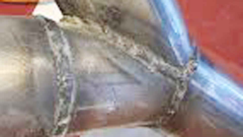
Image by weldingmastermind
Selecting MIG Consumables and Equipment for Exhaust Pipe Work
Exhaust tubing thickness typically falls between 0.049 in. and 0.065 in., so consumable choices directly dictate heat input and penetration without melting edges.
Wire Choices for Mild Steel vs Stainless Exhaust Tubing
For mild steel pipes, 0.023 in. ER70S-6 wire provides the lowest heat input and smoothest feed on short-circuit transfer, reducing burn-through risk on 16-gauge material.
Switch to 0.030 in. only when wall thickness exceeds 0.060 in. or when filling larger gaps in butt joints—0.030 in. carries more amperage per inch of wire but requires tighter voltage control. Stainless exhaust demands 0.023–0.030 in.
ER308LSi or 309LSi wire to match chemistry and prevent cracking from carbon migration. Never substitute mild steel wire on stainless unless the repair is temporary; the joint will rust and fail faster under heat. Dissimilar mild-to-stainless transitions use 309LSi exclusively for its higher ferrite content and crack resistance.
Shielding Gas Selection and Delivery Setup
75% argon/25% CO2 at 20–25 CFH delivers clean short-circuit arcs on mild steel with minimal spatter and good wetting on thin edges. For stainless, tri-mix (90% helium/7.5% argon/2.5% CO2) increases travel speed and reduces oxidation while maintaining low heat.
Pure CO2 works in a pinch but increases spatter and requires 25–30 CFH to shield properly. Set regulator flow to the high side when welding in wind or under the vehicle—anything below 18 CFH invites porosity. Post-flow timer of 8–10 seconds prevents oxidation on the final bead crater.
Welder Capabilities Needed for Thin-Wall Applications
Any 110–220 V MIG machine with true voltage control and at least 140 A output handles exhaust work, but synergic or pulse-capable models simplify parameter selection. Short-circuit mode is mandatory; spray transfer runs too hot.
Machines without inductance control produce harsh arcs that blow holes, dial inductance to the softer side for thin tubing. If your welder lacks pulse, manual stitch timing becomes the primary heat-management tool.
Surface Preparation and Joint Configuration Decisions
Clean metal and tight fit-up account for 70% of weld success on exhaust. Contaminants or gaps amplify heat-related defects.
Effective Cleaning Protocols for Contaminated Exhaust Material
Grind or flap-disc the weld zone to bright metal, removing mill scale, rust, and exhaust carbon 1 in. beyond the joint line on both sides. Follow with a dedicated stainless wire brush—never reuse carbon-steel brushes on stainless to avoid cross-contamination.
Acetone or brake cleaner removes oil films; avoid brake fluid or solvents that leave residue. Inside the pipe, a long wire wheel or compressed air blast clears loose debris that could cause porosity when vaporized.
Gap Control and Fit-Up Techniques That Prevent Defects
Butt joints must maintain less than 1/16 in. gap, use exhaust clamps or temporary tack bridges to pull sections together before welding. Overlap joints (minimum ½ in.) double the material thickness and forgive minor misalignment while distributing heat.
For flange repairs, ensure mating surfaces sit flat; a 0.020 in. gap here turns into a leak path after thermal expansion. Tack every 2–3 in. around the circumference using the same low-heat settings as the final pass, then grind tacks flush to avoid high spots that force the arc to wander.
Establishing MIG Welding Parameters for Exhaust Pipes
Parameters must balance penetration against total heat input. One wrong volt or wire-speed increment creates holes or cold laps.
Baseline Voltage, Amperage, and Wire Feed Speeds for Mild Steel
Start with these values on 16–18 gauge mild steel using 0.023 in. wire and 75/25 gas:
| Thickness (gauge) | Voltage | Wire Feed Speed (IPM) | Approx. Amperage | Travel Speed (IPM) |
|---|---|---|---|---|
| 18 | 15–16.5 | 180–240 | 40–65 | 12–18 |
| 16 | 16–17.5 | 220–280 | 55–80 | 10–15 |
Adjust voltage first for arc length, too long produces spatter and poor wetting; too short causes stubbing. Increase wire feed speed in 10 IPM increments until the puddle flows without undercut. These settings keep heat input under 8–10 kJ/in., critical for preventing distortion in unsupported pipe runs.
Parameter Tweaks for Stainless Steel and Dissimilar Joints
Stainless requires 1–1.5 V lower than mild steel at the same wire speed because its thermal conductivity concentrates heat. Use 14.5–16.5 V and 200–260 IPM with 0.023 in. ER308LSi. For mild-to-stainless transitions, drop voltage another 0.5 V and shorten stick-out to ⅜ in. to concentrate the arc. Tri-mix gas allows slightly higher travel speeds (up to 18 IPM) without sacrificing shielding.
Pulse Mode Advantages in Heat-Sensitive Repairs
If your machine offers pulse or synergic pulse on short-circuit, activate it at 50–70 A peak with 20–30% background. Pulse reduces average heat input by 25–35% while maintaining droplet transfer, letting you run continuous beads on 18-gauge stainless without warping the pipe more than 1/16 in. over 12 in. of weld length. Manual stitchers without pulse must compensate by halving bead length.
Executing MIG Welds on Exhaust Pipes
Technique overrides machine settings once parameters are dialed.
Stitch and Tack Sequencing to Limit Heat Buildup
Weld in ½–¾ in. stitches, pausing 8–12 seconds between segments to let the pipe cool below 300°F. Alternate sides of the joint 180° apart to balance shrinkage. Complete one full circumference in four to six segments rather than chasing a continuous bead.
On long straight sections, skip-weld every third segment first, then fill the gaps after full cooling. This sequence keeps interpass temperature under 250°F and limits total distortion to under 1/8 in. across a 36 in. muffler inlet.
Torch Manipulation for Flat, Vertical, and Overhead Positions
Maintain a 10–15° push angle (torch leading) with ⅜ in. stick-out for flat and vertical-down welds. Overhead demands a 5–10° drag angle and slightly faster travel to prevent puddle sag.
Keep the gun perpendicular to the pipe curvature, any deviation pulls the arc toward the thinner edge and creates undercut. In tight under-car spaces, shorten stick-out to ¼ in. and accept slightly higher spatter for better arc control.
Travel Speed and Arc Length Control for Consistent Beads
Target 10–15 IPM travel on 16-gauge material. Listen for the steady “bacon frying” sound of short-circuit transfer; a popping arc signals voltage too high or speed too slow. Maintain consistent ⅜ in. arc length, any variation changes heat input instantly.
On curved sections, rotate the pipe if possible or walk the cup lightly along the joint line to keep the wire aimed at the leading edge of the puddle.
Solving Field Problems During MIG Exhaust Repairs
Real repairs rarely go perfectly; anticipate and correct these issues on the spot.
Strategies to Eliminate Burn-Through on Thin Sections
Drop voltage 0.5–1 V and shorten stitch length to ⅜ in. if holes appear. Back the gun off to ½ in. stick-out temporarily to soften the arc. If the material is already perforated, bridge the hole with a small patch of same-gauge sheet tacked first, then weld the perimeter in short passes. Pulse mode or 0.023 in. wire almost eliminates this problem once dialed.
Managing Warpage in Long Pipe Runs
Tack the entire assembly in place on the vehicle before final welding to lock alignment. Alternate welding direction every 6 in. and use wet rags or heat sinks (copper backing bars) on the opposite side of the joint when accessible.
For severe warping after cooling, heat the high spot with an oxy-acetylene torch to 600°F and quench strategically, never hammer cold exhaust tubing.
Fixing Porosity and Lack of Fusion in Real-World Conditions
Porosity almost always traces to inadequate cleaning or low gas flow. Grind out porous sections completely and reweld; spot repairs trap contaminants deeper. Lack of fusion appears as a cold line at the toe—raise wire speed 10–20 IPM or slow travel by 2 IPM to increase puddle fluidity without raising voltage.
Finalizing and Verifying MIG Welds on Exhaust Systems
A good-looking bead means nothing if it leaks or corrodes.
Bead Cleanup and Corrosion Protection Methods
Grind the bead flush only where clearance demands it; a slightly convex bead resists cracking better under vibration. Wire-brush hot to remove slag, then apply high-temperature exhaust paint or ceramic coating within 30 minutes of welding while the pipe is still warm. Stainless welds benefit from pickling paste to restore the passive layer and prevent surface rust.
Leak Detection and Pressure Testing Procedures
Pressurize the system to 5–7 psi with shop air after cooling. Use soapy water or an electronic sniffer around every weld—bubbles or readings above background confirm leaks. Fix by grinding back to sound metal and rewelding rather than caulking; exhaust heat destroys sealants quickly.
Deciding Between Welded Repairs and Clamp Alternatives
Permanent MIG welds suit structural cracks and custom fabrications where vibration resistance matters. Use band clamps or V-band flanges for slip joints and easy future disassembly—welded connections complicate catalytic converter or muffler swaps. On catalytic-equipped vehicles, welded repairs upstream of the cat risk contaminating the substrate if slag enters the pipe.
Final Thoughts
Exhaust pipe repairs succeed or fail on heat-management decisions made before the trigger is pulled. Match wire size and voltage to actual wall thickness, sequence stitches around the pipe, and verify fit-up before striking an arc—these choices determine whether the repair lasts 50,000 miles or fails on the first heat cycle.
Professionals who routinely weld performance stainless systems have moved to pulse MIG because it delivers consistent 50–70 A short-circuit transfer with 30–40% less distortion, allowing longer beads without warping the entire assembly.
Apply the same disciplined parameter control and sequencing in the field, and every exhaust repair becomes a repeatable, high-integrity job.
FAQs
What is the best wire size for MIG welding exhaust pipe?
0.023 in. ER70S-6 for mild steel and 0.023–0.030 in. ER308LSi for stainless. It keeps heat low enough to avoid burn-through on 16–18 gauge while providing adequate penetration.
How do I prevent burn-through when MIG welding thin exhaust tubing?
Use 15–17 V, 0.023 in. wire, ½–¾ in. stitches with 8–12 second pauses, and maintain ⅜ in. stick-out. Pulse mode further reduces average heat input.
Can you MIG weld stainless steel exhaust with regular mild steel wire?
Yes for temporary or budget repairs, but the joint loses corrosion resistance and may crack under thermal cycling. Use 309LSi filler for permanent dissimilar or stainless-to-stainless welds.
What gas mixture works best for MIG welding exhaust pipes?
75/25 argon/CO2 for mild steel; tri-mix (90% He / 7.5% Ar / 2.5% CO2) for stainless. Set flow at 20–25 CFH and ensure 8–10 seconds post-flow.

Hi, I’m Zachary Ford. I’m passionate about welding and dedicated to helping both beginners and experienced welders make informed decisions. I research, test, and write about welding helmets, welding machines, safety equipment, and essential workshop tools. My goal is to provide honest reviews, practical buying guides, and easy-to-follow tutorials that help you weld more safely, work more efficiently, and choose the right gear with confidence.