Accurately managing shielding gas is critical in MIG welding, directly affecting arc stability, weld quality, and overall operating cost. Understanding How To Calculate Gas Consumption In MIG Welding helps prevent common issues like porosity, inconsistent bead appearance, and unnecessary gas waste.
In real fabrication environments, incorrect flow rates or poor estimation can lead to excess consumption, increased downtime for cylinder changes, and failed inspections due to contamination.
Gas consumption isn’t just about setting a flowmeter, it involves calculating flow rate, arc time, and efficiency based on actual welding conditions. Whether you’re working on light fabrication or heavy structural welds, knowing how to estimate gas usage ensures better cost control and consistent weld performance.
This guide clarifies the calculation process and the factors that influence gas consumption, so you can optimize shielding effectiveness while minimizing waste in practical welding scenarios.
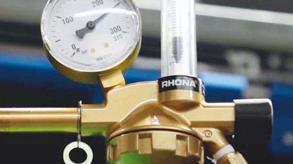
Image by binzel-abicor
Choosing the Correct Gas Flow Rate for Your MIG Setup
Flow rate is the single variable you set on the regulator that determines everything else in the consumption equation. It must deliver enough shielding without exceeding the point where turbulence contaminates the pool.
Flow Rate Recommendations by Material and Conditions
Start with these proven ranges measured at the nozzle during welding:
- Mild steel (75/25 Ar/CO₂ or C25 mix), indoor still air: 10–15 CFH (4.7–7 L/min).
- Mild steel, light draft or overhead: 18–22 CFH (8.5–10.4 L/min).
- Stainless steel: 20–30 CFH (9.4–14 L/min).
- Aluminum (pure argon): 25–35 CFH (11.8–16.5 L/min).
Outdoor or fan-driven shop air requires an immediate +10–15 CFH increase. Spray transfer modes on thicker plate push toward the upper end because higher wire speeds and amperage increase pool size and gas demand.
Nozzle Size Limits That Prevent Turbulence
Nozzle internal diameter caps safe maximum flow before the gas column becomes turbulent and sucks atmospheric oxygen into the weld:
| Nozzle ID | Maximum Safe Flow (CFH) | Typical Use Case |
|---|---|---|
| 3/8 inch | 30 | Thin gauge, short-circuit transfer |
| 1/2 inch | 40 | General mild steel production |
| 5/8 inch | 55 | Spray transfer, thicker plate |
| 3/4 inch | 65 | Outdoor or high-draft aluminum |
Exceeding these values for your nozzle size is the most common hidden cause of porosity even when the gauge reads “high flow.” Test any new setting on scrap first: if the bead shows oxidation or random pores after 6 inches, drop 3–5 CFH and retest.
The Fundamental Formula to Calculate MIG Gas Consumption
The core equation is straightforward and works for every machine and material once you know arc time.
Gas consumed (CF) = Flow rate (CFH) × Arc time (hours)
Gas consumed (liters) = Flow rate (L/min) × Arc time (minutes)
Arc time is not clock time. It equals total weld length divided by your actual travel speed. Example: 40 feet of 1/4-inch fillet at 12 inches per minute travel speed = 480 inches ÷ 12 ipm = 40 minutes = 0.667 hours. At 20 CFH flow, consumption = 20 × 0.667 = 13.34 cubic feet.
Accounting for Pre-Flow, Post-Flow, and Multiple Starts
Modern machines add 0.5–1 second pre-flow and 10–20 seconds post-flow per trigger pull. With 15 starts on a multi-pass job, that extra time adds measurable volume.
Calculation adjustment: Add (pre-flow seconds + post-flow seconds) × number of starts ÷ 3600 × flow rate (CFH).
For the 40-foot job above with 15 starts, 1 s pre + 15 s post = 16 s × 15 = 240 seconds = 0.067 hours extra. At 20 CFH this equals 1.34 CF additional. Total gas = 13.34 + 1.34 = 14.68 CF.
Duty cycle further scales real consumption. A 200 A machine at 60 % duty cycle running 8 clock hours actually delivers only 4.8 hours of arc time. Multiply your arc-time result by the duty-cycle percentage.
Using Wire Consumption to Predict Gas Needs Accurately
The gas-to-wire ratio method gives tighter estimates when you already know wire usage or spool size—ideal for quoting or production planning.
Typical ratio for 75/25 mix on mild steel: 4–5 cubic feet of gas per pound of wire deposited.
Derivation example (0.045-inch wire at 300 ipm WFS):
- Wire melts at approximately 8.14 lb/hr.
- At 35 CFH flow, ratio = 35 ÷ 8.14 ≈ 4.3 CF per lb.
Scale to your settings:
- 0.030-inch wire, 200 ipm WFS → ~4.5 lb/hr deposition → 20 CFH flow → ratio ≈ 4.4 CF/lb.
- 0.035-inch wire, 250 ipm WFS on 1/8-inch plate → ~6.8 lb/hr → 22 CFH → ratio ≈ 3.2 CF/lb (spray transfer improves efficiency).
For a 15 kg (33 lb) spool of 0.035-inch ER70S-6 at 4.4 CF/lb ratio, expect 145 CF total gas once you add 10 % for pre/post-flow and minor leaks. This matches real shop refill logs within 8 %.
Adjusting Calculations for Real Shop Conditions
Drafts, Welding Position, and Joint Type
Drafts are the largest variable. A 4–5 mph cross breeze (common near open shop doors) can double effective consumption because you must raise flow 10–15 CFH to maintain coverage.
Overhead fillets lose gas faster than flat-position beads; add 5 CFH or 15 % to the base calculation. Lap joints retain gas better than open butt joints—reduce flow by 3–5 CFH once you confirm no porosity on test pieces.
Gas Mixture Effects on Consumption Volume
Pure CO₂ is denser and allows slightly lower flow settings (15–20 CFH) on mild steel but produces more spatter that can clog nozzles and indirectly raise usage.
Argon-rich mixes (90 % Ar) are lighter, require tighter nozzle control, and often need 2–3 CFH more to compensate. Helium blends for aluminum increase flow demand another 5–8 CFH because helium rises rapidly.
Sizing Gas Cylinders Based on Your Welding Volume
Cylinder capacity is stamped on the shoulder in cubic feet (water capacity converted at standard pressure). Usable volume is roughly 80–85 % before pressure drops too low for consistent flow.
| Cylinder Designation | Nominal Capacity (CF) | Usable Volume (CF) | Approx. Hours at 20 CFH (50 % duty cycle) |
|---|---|---|---|
| R / 20 cu ft | 20 | 16 | 1.6 hours |
| Q / 80 cu ft | 80 | 65 | 6.5 hours |
| S / 125 cu ft | 125 | 105 | 10.5 hours |
| T / 300 cu ft | 300 | 250 | 25 hours |
Runtime formula: Usable CF ÷ (Flow rate × Duty cycle factor).
A hobbyist running 0.035-inch wire at 18 CFH and 40 % duty cycle on an 80 CF cylinder gets approximately 9 hours of actual trigger time—enough for two full weekends of trailer frame work.
Track usage by logging initial and final gauge pressure. Volume used = (Start PSI – End PSI) ÷ (Full PSI ÷ Nominal CF). This method beats estimation when you switch between machines or operators.
Monitoring and Verifying Consumption in Practice
Install an inline flowmeter at the gun end (not just the regulator) to read true nozzle delivery. Pressure drops across long hoses or spatter-clogged diffusers can cut actual flow 20–30 % even when the regulator shows 20 CFH.
Weigh cylinders before and after large jobs for the most accurate audit—argon weighs 0.103 lb per cubic foot at standard temperature.
For production runs, batch similar joints to minimize starts and post-flow waste. Pulsed MIG machines with synchronized gas delivery can cut total consumption 15–20 % compared with constant-voltage spray while maintaining the same deposition rate.
Performance-based Takeaway
Running the numbers before every job lets you choose the exact cylinder size and flow setting that matches your real arc time and duty cycle. A fabricator who calculates 105 CF for a structural skid and orders the 125 CF cylinder instead of two 80 CF bottles saves a full day of downtime and $45–60 in refill labor.
Once you master gas-to-wire ratios, integrate them with modern pulsed waveforms that deliver gas only during peak current pulses.
Shops using this synchronized approach report 18–22 % lower monthly gas invoices without sacrificing bead appearance or mechanical properties, turning a basic cost center into a measurable productivity gain.

Hi, I’m Zachary Ford. I’m passionate about welding and dedicated to helping both beginners and experienced welders make informed decisions. I research, test, and write about welding helmets, welding machines, safety equipment, and essential workshop tools. My goal is to provide honest reviews, practical buying guides, and easy-to-follow tutorials that help you weld more safely, work more efficiently, and choose the right gear with confidence.